Setup & Operation 14. Option Slots
106 RC700 / RC700-A Rev.23
14.8.1 Notes on the EUROMAP67 Board
The EUROMAP67 board contains 15 inputs and 16 outputs on a single substrate.
You can install up to two
EUROMAP67 board in the controller.
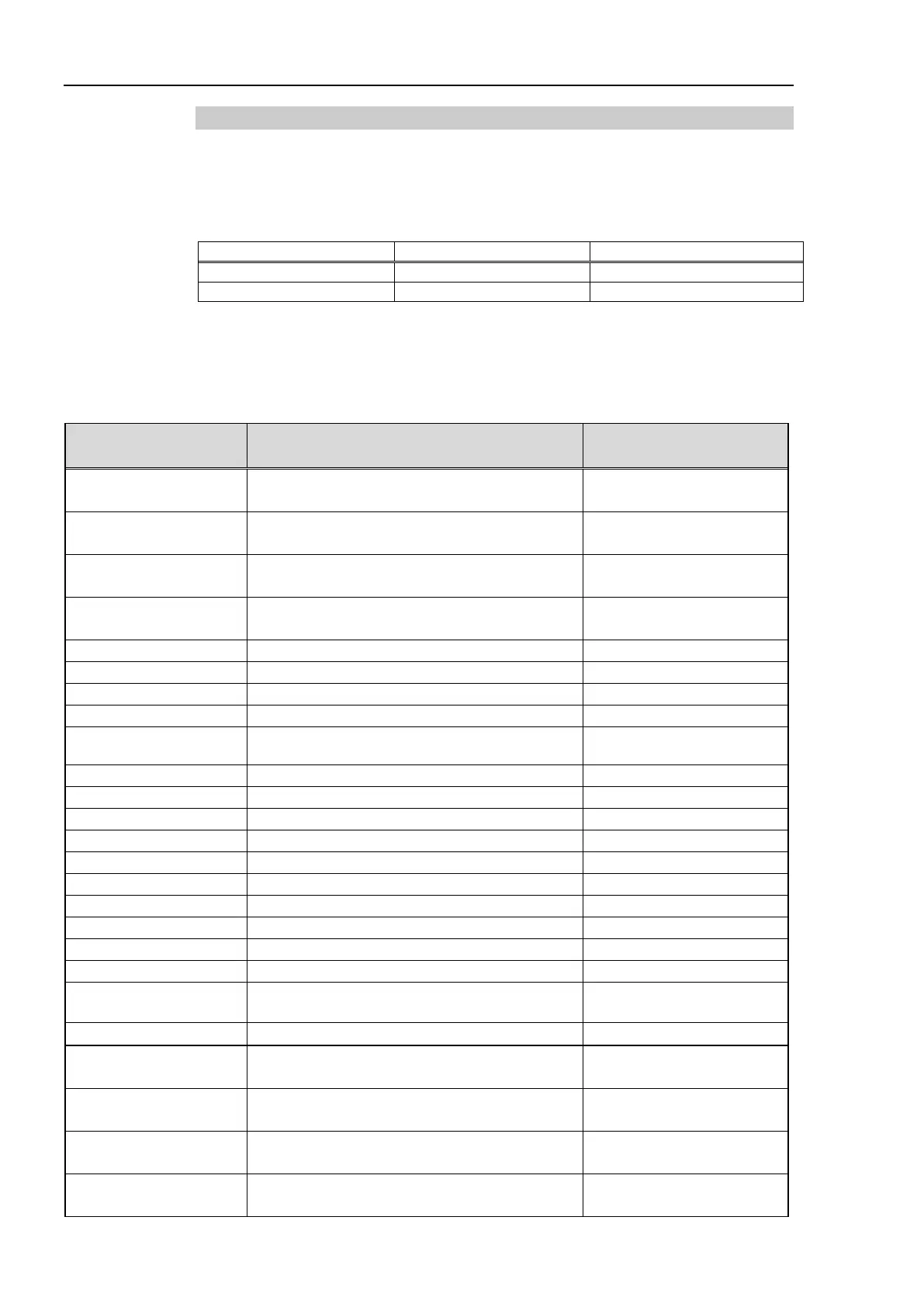
The input and output bit numbers are assigned as follows.
Outputs No.205 and No.237 are not used. However, the EUROMAP standard describes
that they may potentially be used in the future.
EUROMAP67 pin definitions
EUROMAP connecter
(CN4) Pin No.
Signal Name Note
ZC1
Emergency stop of machine channel1
ZC2
Emergency stop of machine channel2
ZC3
Safety devices of machine channel1
ZC4
Safety devices of machine channel2
Intermediate mold opening position
ZA9 Supply from handling device / robot
Enable operation with handing device / robot
Core pullers 1 in position 1
Core pullers 1 in position 2
Core pullers 2 in position 1
Core pullers 2 in position 2
Reserved for future use by EUROMAP
Reserved for future use by EUROMAP
Reserved for future use by EUROMAP
ZC8
Not fixed by EUROMAP, manufacturer
dependent
I/O Input (*1)
Supply from handling device / robot
C1
Emergency stop of robot channel1
A2
Emergency stop of robot channel2
C3
Mold area free
A4
C4
Reserved for future use by EUROMAP

 Loading...


