Safety 3. Installation
32 RC700 / RC700-A Rev.23
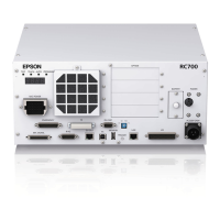
Connector for 200VAC power input to the Controller.
The cable with connector on the Controller side.
Connect the Manipulator and the M/C POWER connector on the Controller. Insert
the connectors until you hear a “click”.
The cable with connector on the Controller side.
Connect the Manipulator and the M/C SIGNAL connector on the Controller.
The EMERGENCY connector has inputs to connect the Emergency Stop switch
and the Safety Door switch. For safety reasons, connect proper switches for these
input devices.
For details, refer to the Setup & Operation 9. EMERGENCY.
Connect the PC for development.
For details, refer to the Setup & Operation 5. Development PC Connection USB
Port.
Connect the USB memory.
For details, refer to the Setup & Operation 6. Memory Port.
LAN (EtherNet Communication)
Connect the EtherNet cable.
For details, refer to the Setup & Operation 7. LAN (Ethernet Communication) Port.
This connector is used for input/output devices of the user.
When there are input/output devices, use this connector.
There are I/O cable (option) and terminal block (option) for the I/O connector.
For details, refer to the Setup & Operation 11. I/O Connector.
Connect the option Teach Pendant.
For details, refer to the Setup & Operation 8.TP Port.
This port is used for the RS-232C communication with external devices.
For details, refer to Setup & Operation 10. Standard RS-232C Port.
This connector is used for connecting with input signals necessary for real time I/O
function.
For details, refer to the Setup & Operation 13. R-I/O Connector.

 Loading...