11 16-BIT TIMERS (T16)
11-6
Seiko Epson Corporation
S1C17624/604/622/602/621 TECHNICAL MANUAL
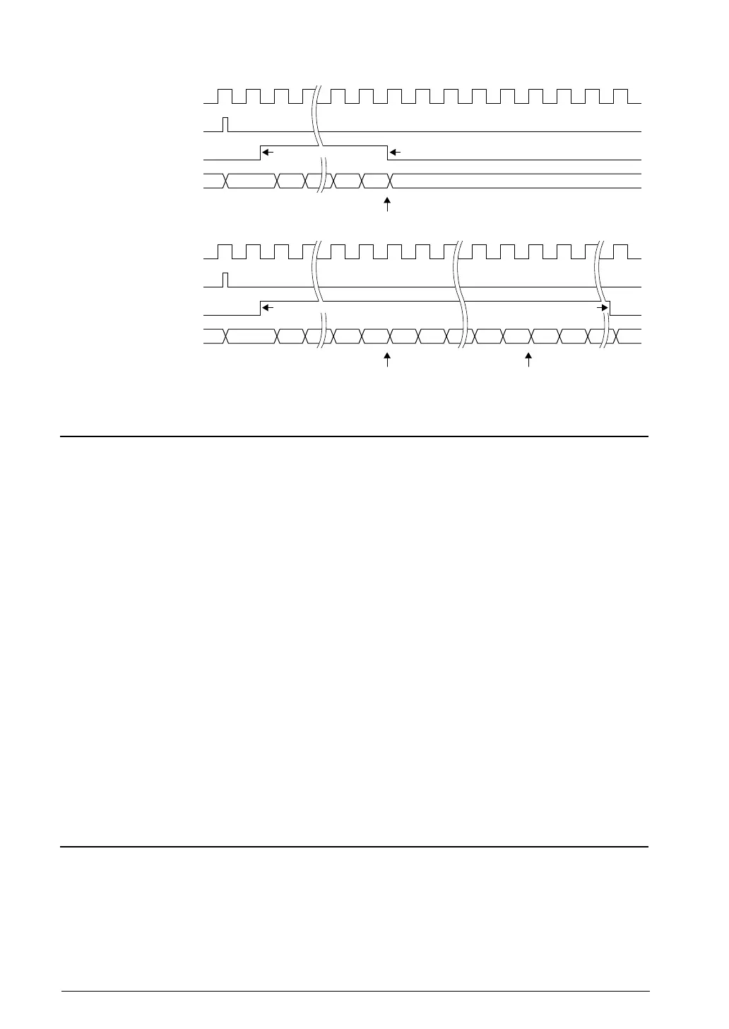
Count clock
PRESER write
PRUN
Counter
Interrupt request
01n-1n n
Count clock
PRESER write
PRUN
Counter
Interrupt request
01n-1n n 01n-1 n n-1
One-shot mode
Repeat mode
Reset by hardwareSet by software
Set by software
Reset by software
7.1 Count OperationFigure 11.
T16 Output Signals11.8
The T16 module outputs underflow pulses when the counter underflows.
These pulses are used for timer interrupt requests.
These pulses are also used to generate the serial transfer clock for the internal serial interface or the A/D conversion
trigger signal.
The clock generated is sent to the internal peripheral module, as shown below.
T16 Ch.0 out
put clock → A/D converter
T16 Ch.1 output clock → SPI
T16 Ch.2 output clock → I
2
C master
Use the following equations to calculate the reload data register value for obtaining the desired transfer rate or A/D
conversion interval:
ct_clk
SPI TR = —————— - 1
bps × 2
ct_clk
I
2
C master TR = —————— - 1
bps × 4
ct_clk × adi
A/D converter TR = —————— - 1
2
ct_clk: Count clock frequency (Hz)
TR: Reload data (0–65535)
bps: T
ransfer rate (bits/s)
adi: A/D conversion interval (s)
T16 Interrupts11.9
Each channel of the T16 module outputs an interrupt request to the interrupt controller (ITC) when the counter un-
derflows.
Underflow interrupt
When the counter underflows, the interrupt flag T16IF/T16_INTx register, which is provided for each channel
in the T16 module, is set to 1. At the same time, an interrupt request is se
nt to the ITC if
T16IE/T16_INTx reg-
ister has been set to 1 (interrupt enabled).
An interrupt is generated if the ITC and S1C17 Core interrupt condi-
tions are satisfied.



 To Next Page