13 16-BIT PWM TIMERS (T16A2)
13-8
Seiko Epson Corporation
S1C17624/604/622/602/621 TECHNICAL MANUAL
Reading Counter Values13.5.3
The counter value can be read from T16ATC[15:0]/T16A_TCx register even if the counter is running. However, the
counter value should be read at once using a 16-bit transfer instruction. If data is read twice using an 8-bit transfer
instruction, the correct value may not be obtained due to occurrence of count up between readings.
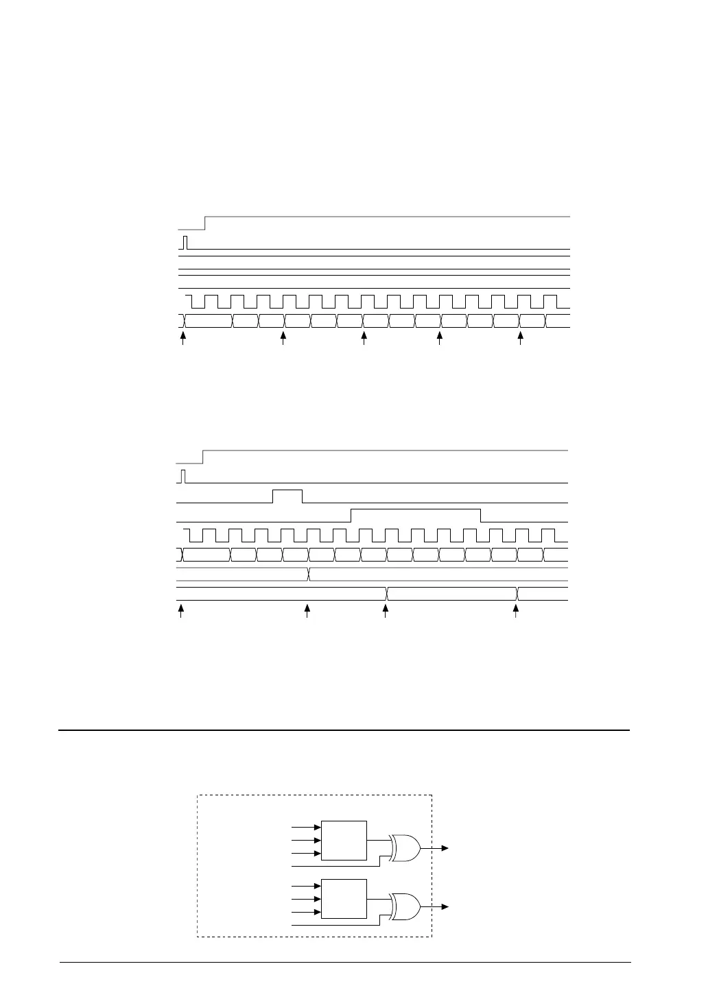
Counter Operation and Interrupt Timing Charts13.5.4
Comparator mode
PRUN
PRESET
T16A_CCAx
T16A_CCBx
Count clock
T16A_TCx
Reset Compare A
interrupt
Reset and
compare B
interrupt
Compare A
interrupt
Reset and
compare B
interrupt
012 3 4 5 0 1 2 3 4 5 0 1
0x2
0x5
5.4.1 Operation Timing in Comparator ModeFigure 13.
Capture mode
PRUN
PRESET
CAP(A)
CAP(B)
Count clock
T16A_TCx
T16A_CCAx
T16A_CCBx
(when CAPATRG[1:0] = 0x1, CAPBTRG[1:0] = 0x3)
Reset Capture A
interrupt
Capture B
interrupt
Capture B
interrupt
(and capture B overwrite
interrupt if CAPBIF = 1)
012 3 4 5 6 7 8 9 10 11 12 13
3
6 11
5.4.2 Operation Timing in Capture ModeFigure 13.
Timer Output Control13.6
The timer that has been set in comparator mode can generate TOUT signals using the compare A and compare B
signals and can output it to external devices. Each timer channel provides two TOUT outputs, thus the T16A2 mod-
ule can output up to four TOUT signals. Figure 13.6.1 shows the TOUT output circuit (one timer channel).
TOUT A
output
control
Compare A signal
Compare B signal
TOUTAMD[1:0]
TOUTAINV
TOUTAx
TOUT B
output
control
Compare A signal
Compare B signal
TOUTBMD[1:0]
TOUTBINV
TOUTBx
Comparator/capture block Ch.x
6.1 TOUT Output Circuit Figure 13.
 Loading...