24 A/D CONVERTER (ADC10)
24-10
Seiko Epson Corporation
S1C17624/604/622/602/621 TECHNICAL MANUAL
When ADMS is 0, the A/D converter operates in one-time conversion mode. In this mode, A/D conver-
sion is terminated after all inputs in the range of the channels selected by ADCS[2:0] and ADCE[2:0]
have been converted once.
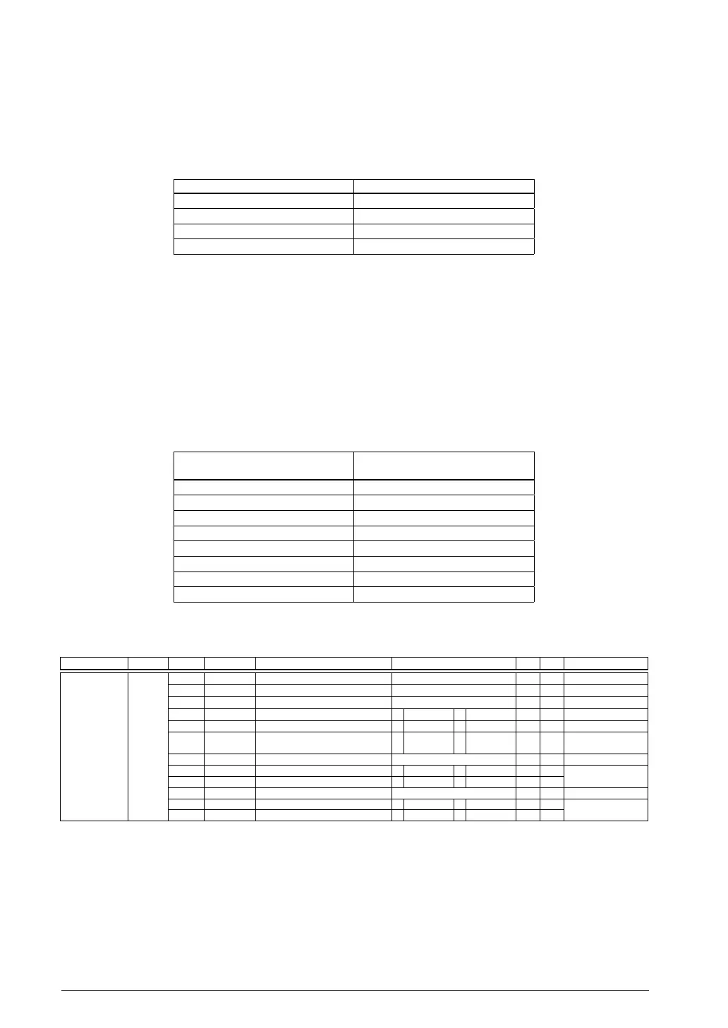
D[5:4] ADTS[1:0]: Conversion Trigger Select Bits
Selects a trigger source to start A/D conversion.
6.3 Trigger Selection Table 24.
ADTS[1:0] Trigger source
0x3 External trigger (#ADTRG)
0x2 Reserved
0x1 16-bit timer Ch.0
0x0 Software trigger
(Default: 0x0)
When an external trigger is used, the #ADTRG pin must be configured in advance using the port func-
tion select bit (see the “I/O Ports (P)” chapter). A/D conversion is started when a falling edge of the
#ADTRG signal is detected.
When 16-bit timer (T16) Ch.0 is used, since its u
nderflow signal serves as a trigger, set the underflow
cycle and other conditions for the timer.
D3 Reserved
D[2:0] ADST[2:0]: Sampling Time Setting Bits
Sets the analog input sampling time.
6.4 Sampling Time Settings Table 24.
ADST[2:0]
Sampling time
(in A/D conversion clock cycles)
0x7 9 cycles
0x6 8 cycles
0x5 7 cycles
0x4 6 cycles
0x3 5 cycles
0x2 4 cycles
0x1 3 cycles
0x0 2 cycles
(Default: 0x7)
A/D Control/Status Register (ADC10_CTL)
Register name Address Bit Name Function Setting Init. R/W Remarks
A/D Control/
Status Register
(ADC10_CTL
)
0x5384
(16 bits)
D15
–
reserved – – – 0 when being read.
D14–12
ADICH[2:0]
Conversion channel indicator 0x0 to 0x7 0x0 R
D11
–
reserved – – – 0 when being read.
D10
ADIBS
ADC10 status 1 Busy 0
Idle
0 R
D9
ADOWE
Overwrite error flag 1 Error 0 Normal 0 R/W Reset by writing 1.
D8
ADCF
Conversion completion flag 1 Completed 0 Run/Stand-
by
0 R Reset when ADC10_
ADD is read.
D7–6
–
reserved – – – 0 when being read.
D5
ADOIE
Overwrite error interrupt enable 1 Enable 0 Disable 0 R/W
D4
ADCIE
Conversion
completion int. enable 1 Enable 0 Disable 0 R/W
D3–2
–
reserved – – – 0 when being read.
D1
ADCTL
A/D conversion control 1 Start 0 Stop 0 R/W
D0
ADEN
ADC10 enable 1 Enable 0 Disable 0 R/W
D15 Reserved
D[14:12] ADICH[2:0]: Conversion Channel Indicator Bits
Indicates the channel number (0 to 7) currently being A/D-converted. (Default: 0x0 = AIN0)
When A/D conversion is performed in multiple channels, read this bit to identify the channel in which
conversion is underway.
D11 Reserved
 Loading...