9 I/O PORTS (P)
S1C17624/604/622/602/621 TECHNICAL MANUAL
Seiko Epson Corporation
9-5
6.1 Chattering Filter Function SettingsTable 9.
PxCF1[2:0]/PxCF2[2:0] Check time *
0x7 16384/fPCLK (8 ms)
0x6 8192/f
PCLK (4 ms)
0x5 4096/f
PCLK (2 ms)
0x4 2048/f
PCLK (1 ms)
0x3 1024/f
PCLK (512 µs)
0x2 512/f
PCLK (256 µs)
0x1 256/f
PCLK (128 µs)
0x0 No check time (off)
(Default: 0x0, * when PCLK = 2 MHz)
Notes: • An unexpected interrupt may occur after SLEEP status is canceled if the slp instruction is
executed while the chattering filter function is enabled. The c
hattering filter must be disabled
before placing the CPU into SLEEP status.
• The chattering filter check time refers to the maximum pulse width that can be filtered.
Generating an input interrupt requires a minimum input time of the check time and a maximum
input time of twice the check time.
• The Px port interrupt must be disabled before setting the Px_CHAT register. Setting the regis-
ter while
the interrupt is enabled may generate inadvertent Px port interrupt. Also the chatter-
ing filter circuit requires a maximum of twice the check time for stabilizing the operation status.
Before enabling the interrupt, make sure that the stabilization time has elapsed.
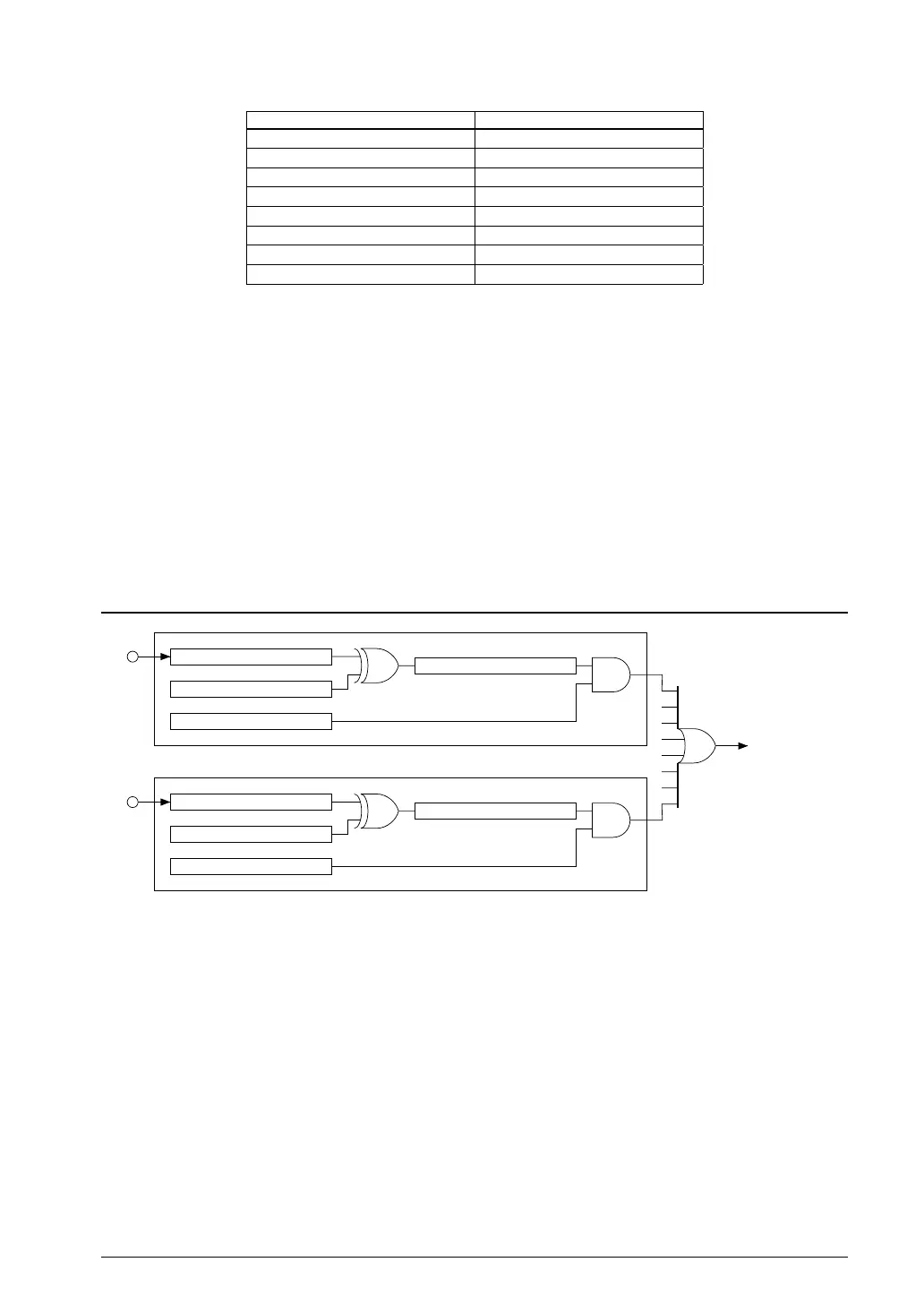
Port Input Interrupt9.7
Px port
interrupt request
(to ITC)
(Px = P0 and P1)
Chattering filter
Interrupt flag
Interrupt enable
Interrupt edge selection
Px0
PxCF1[2:0]
PxEDGE0
PxIF0
PxIE0
Px7
PxCF2[2:0]
PxEDGE7
PxIF7
PxIE7
• • •
7.1 Port Input Interrupt Circuit ConfigurationFigure 9.
The P0 and P1 ports include input interrupt functions.
Select which of the 16 ports are to be used for interrupts based on requirements. You can also select whether inter-
rupts are generated for either the rising edge or falling edge of the input signals.
Interrupt port selection
Select the port generating an interrupt using PxIEy/Px_IMSK register.
Setting PxIEy to 1 enables interrupt generation by the corresponding port. Setting to 0 (default) disables inter-
rupt generation.
Interrupt edge selection
Port input interrupts can be generated at either the rising edge or falling edge of the input signal. Select the edge
used to generate interrupts using PxEDGEy/Px_EDGE register.
Setting PxEDGEy to 1 generates port input interrupts at the inp
ut signal falling edge. Setting it to 0 (default)
generates interrupts at the rising edge.



 To Next Page