28 MULTIPLIER/DIVIDER (COPRO)
S1C17624/604/622/602/621 TECHNICAL MANUAL
Seiko Epson Corporation
28-1
Multiplier/Divider (COPRO)28
Overview28.1
The S1C17624/604/622/602/621 has an embedded coprocessor that provides multiplier/divider functions.
The following shows the features of the multiplier/divider:
• Multiplication: Supports signed/unsigned multiplications.
(16 bits × 16 bits = 32 bits)
Can be executed in 1 cycle.
• Multiplication and accumulation (MAC): Supports signed MAC operations with
overflow detection function.
(16 bits × 16 bits + 32 bits = 32 bits)
Can be executed in 1 cycle.
• Division: Supports signed/unsigned divisions.
(16 bits ÷ 16 bits = 16 bits with 16-bit residue)
Can be executed in 17 to 20 cycles.
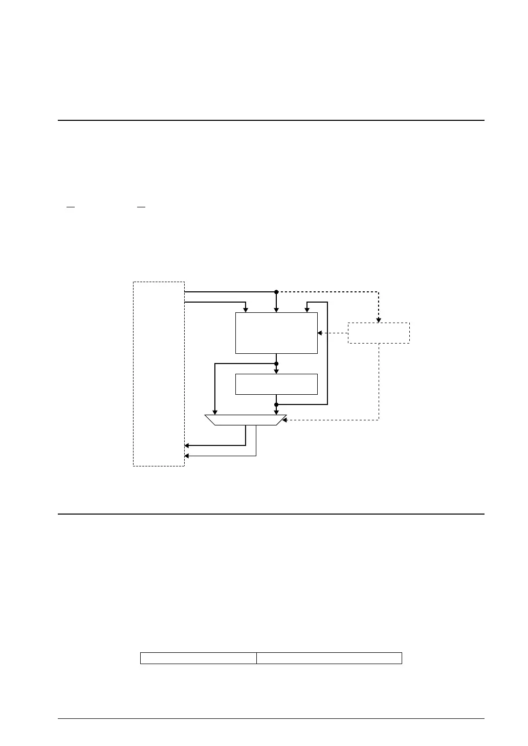
S1C17 Core
Arithmetic unit
Operation result
register
Mode setting
Selector
Argument 2
Argument 1
Coprocessor
output
Flag output
Operation
result
1.1 Multiplier/Divider Block DiagramFigure 28.
Operation Mode and Output Mode28.2
The Multiplier/divider operates according to the operation mode specified by the application program. As listed in
Table 28.2.1, the multiplier/divider supports nine operations.
The multiplication, division and MAC results are 32-bit data, therefore, the S1C17 Core cannot read them in one
access cycle. The output mod
e is provided to specify the high-order 16 bits or low-order 16 bits of the operation
results to be read from the multiplier/divider.
The operation and output modes can be specified with a 7-bit data by writing it to the mode setting register in the
multiplier/divider. Use a “ld.cw” instruction for this writing.
ld.cw %rd,%rs %rs[6:0] is written to the mode setting register. (%rd: not used)
ld.cw %rd,imm7 imm7[6:0] is written to
the mode setting register. (%rd: not used)
6 4 3 0
Output mode setting value Operation mode setting value
2.1 Mode Setting RegisterFigure 28.



 To Next Page