9 I/O PORTS (P)
9-6
Seiko Epson Corporation
S1C17624/604/622/602/621 TECHNICAL MANUAL
Interrupt flags
The ITC is able to accept two interrupt requests from the P0 and P1 ports, and the P port module contains inter-
rupt flags PxIFy/Px_IFLG register corresponding to the individual 16 ports to enable individual control of the
16 Pxy port interrupts. PxIFy is set to 1 at the specified edge (rising or falling edge) of the input signal. If the
corresponding PxIEy has been set to 1, an int
errupt request signal is also output to the ITC at the same time. An
interrupt is generated if the ITC and S1C17 Core interrupt conditions are satisfied.
PxIFy is reset by writing 1.
For specific information on interrupt processing, see the “Interrupt Controller (ITC)” chapter.
Notes: • The P port module interrupt flag PxIFy must be reset in the interrupt handler routine after a
port interrupt has occu
rred to prevent recurring interrupts.
• To prevent generating unnecessary interrupts, reset the relevant PxIFy before enabling inter-
rupts for the required port using PxIEy.
P0 Port Key-Entry Reset 9.8
Entering low level simultaneously to the ports (P00–P03) selected with software triggers an initial reset. The ports
used for the reset function can be selected with the P0KRST[1:0]/P0_KRST register
.
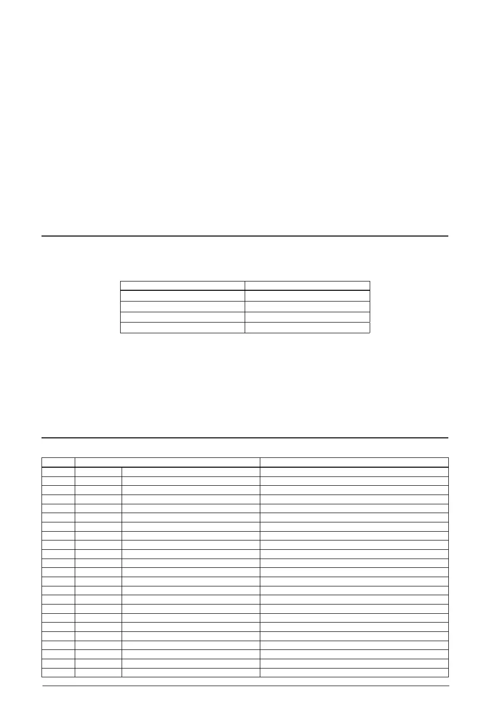
8.1 Configuration of P0 Port Key-Entry ResetTable 9.
P0KRST[1:0] Port used for resetting
0x3 P00, P01, P02, P03
0x2 P00, P01, P02
0x1 P00, P01
0x0 Not used
(Default: 0x0)
For example, if P0KRST[1:0] is set to 0x3, an initial reset will take place when the four ports P00–P03 are set to
low level at the same time.
Note: The P0 port key-entry reset function cannot be used for power-on reset as it must be enabled with
software.
Control Register Details9.9
9.1 List of I/O Port Control RegistersTable 9.
Address Register name Function
0x5200 P0_IN P0 Port Input Data Register P0 port input data
0x5201 P0_OUT P0 Port Output Data Register P0 port output data
0x5202 P0_OEN P0 Port Output Enable Register Enables P0 port outputs.
0x5203 P0_PU P0 Port Pull-up Control Register Controls the P0 port pull-up resistor.
0x5204 P0_SM P0 Port Schmitt Trigger Control Register Controls the P0 port Schmitt trigger input.
0x5205 P0_IMSK P0
Port Interrupt Mask Register Enables P0 port interrupts.
0x5206 P0_EDGE P0 Port Interrupt Edge Select Register Selects the signal edge for generating P0 port interrupts.
0x5207 P0_IFLG P0 Port Interrupt Flag Register Indicates/resets the P0 port interrupt occurrence status.
0x5208 P0_CHAT P0 Port Chattering Filter Control Register Controls the P0 port chattering filter.
0x5209 P0_KRST
P0 Port Key-Entry Reset Configuration Register
Configures the P0 port key-entry reset function.
0x520a P0_IEN
P0 Port Input Enable Register
Enables P0 port inputs.
0x5210 P1_IN P1 Port Input Data Register P1 port input data
0x5211 P1_OUT P1 Port Output Data Register P1 port output data
0x5212 P1_OEN P1 Port Output Enable Register Enables P1 port outputs.
0x5213 P1_PU P1 Port Pull-up Control Register Controls the P1 port pull-up resistor.
0x5214 P1
_SM P1 Port Schmitt Trigger Control Register Controls the P1 port Schmitt trigger input.
0x5215 P1_IMSK P1 Port Interrupt Mask Register Enables P1 port interrupts.
0x5216 P1_EDGE P1 Port Interrupt Edge Select Register Selects the signal edge for generating P1 port interrupts.
0x5217 P1_IFLG P1 Port Interrupt Flag Register Indicates/resets the P1 port interrupt occurrence status.
0x5218 P1_CHAT P1 Port Chattering F
ilter Control Register Controls the P1 port chattering filter.
0x521a P1_IEN
P1 Port Input Enable Register
Enables P1 port inputs.
0x5220 P2_IN P2 Port Input Data Register P2 port input data
0x5221 P2_OUT P2 Port Output Data Register P2 port output data



 To Next Page