8 REAL-TIME CLOCK (RTC)
S1C17624/604/622/602/621 TECHNICAL MANUAL
Seiko Epson Corporation
8-9
Also be sure to write 1 to RTCIRQ to reset it.
When a software reset is performed (RTCRST → 1 → 0), RTCIRQ and RTCIEN are reset to 0 to disable the
interrupt request output. Also RTCT[2:0] is reset to 0x1.
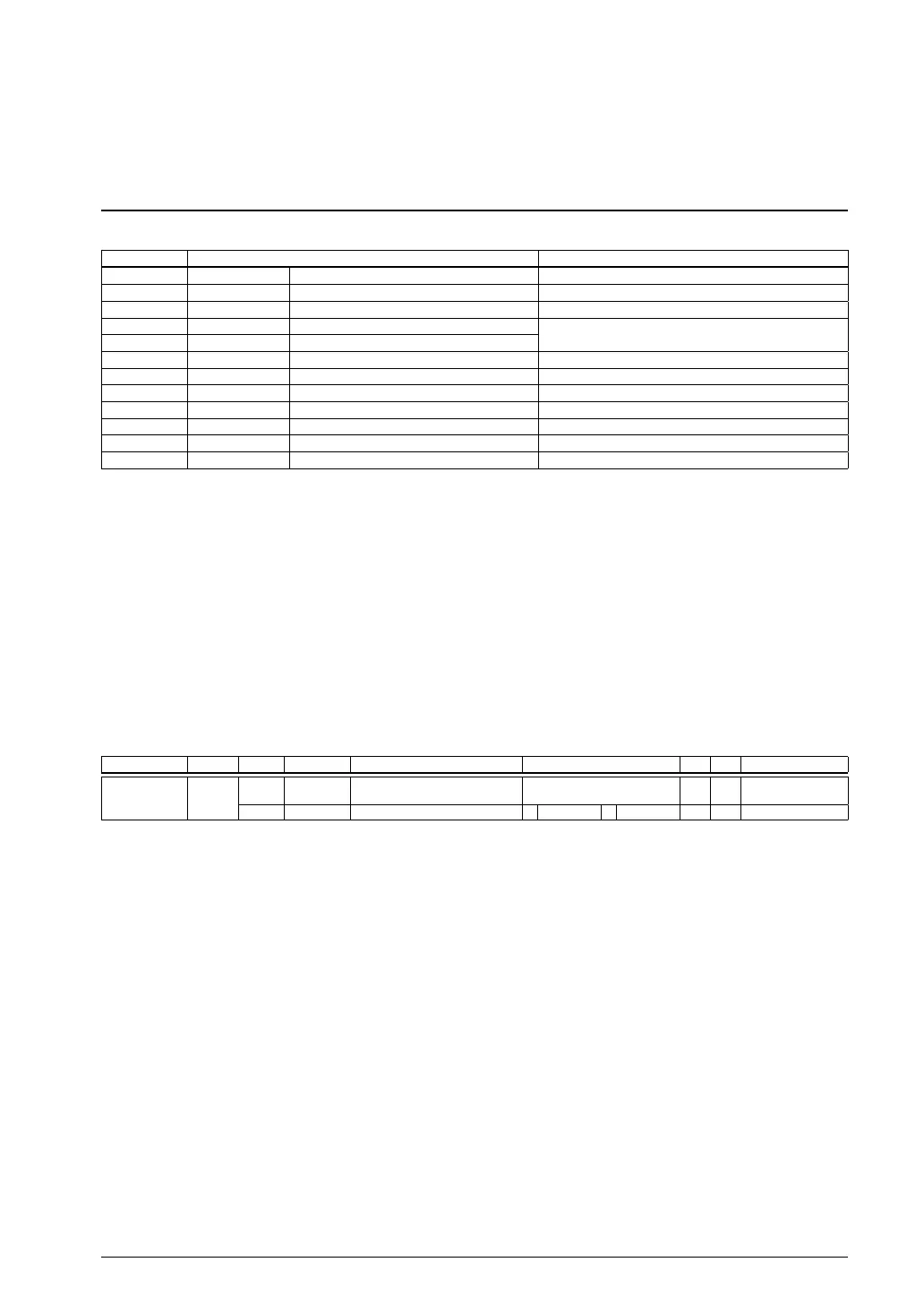
Details of Control Registers8.5
5.1 RTC Register ListTable 8.
Address Register name Function
0x506e RTC_CC RTC Clock Control Register Controls the RTC clock source.
0x5140 RTC_INTSTAT RTC Interrupt Status Register Indicates RTC interrupt status.
0x5141
RTC_INTMODE
RTC Interrupt Mode Register Sets up RTC interrupt modes.
0x5142 RTC_CNTL0 RTC Control 0 Register Controls the RTC.
0x5143 RTC_CNTL1 RTC Control 1 Register
0x5144 RTC_SEC RTC Second Register Second counter data
0x5145 RTC_MIN
RTC Minute Register Minute counter data
0x5146 RTC_HOUR RTC Hour Register Hour counter data
0x5147 RTC_DAY RTC Day Register Day counter data
0x5148 RTC_MONTH RTC Month Register Month counter data
0x5149 RTC_YEAR RTC Year Register Year counter data
0x514a RTC_WEEK RTC Days of Week Register Days of week counter data
The following describes each RTC register. These are all 8-bit registers.
Notes: • When data is written to the
register, the “Reserved” bits must always be written as 0 and not 1.
• The contents of all RTC control registers are indeterminate when power is turned on, and are
not initialized to specific values by initial reset. These registers should be initialized in software.
• If 1 is being carried over when the counters are accessed for read, the correct counter value
may not be read out. Moreover, attem
pting to write to a counter or other control register may
corrupt the counter value. Therefore, do not write to counters while 1 is being carried over. For
the correct method of operation, see Section 8.3.5, “Counter Hold and Busy Flag,” and Section
8.3.7, “Counter Read.”
RTC Clock Control Register (RTC_CC)
Register name Address Bit Name Function Setting Init. R/W Remarks
RTC Clock
Control Register
(RTC_CC)
0x506e
(8 bits)
D7–1
–
reserved – – – 0 when being read.
D0
RTCCE
RTC clock enable 1 Enable 0 Disable 0 R/W
D[7:1] Reserved
D0 RTCCE: RTC Clock Enable Bit
Enables or disables the OSC1 clock supply to the RTC.
1 (R/W): Enabled (on)
0 (R/W): Disabled (off) (default)
The RTCCE default setting is 0, which disables the clock supply. Setting RTCCE to 1 sends the OSC1
clock to the RTC. When the OSC1 oscillator circuit is stopped, writing 1 to RTCCE turns it on (note,
how
ever, that the OSC1 clock is not supplied to other peripheral circuits than the RTC). When RTCCE
is set to 1, the OSC1 oscillator circuit does not stop even if the IC enters SLEEP mode (the OSC1 clock
will be supplied to the RTC only).
When RTCCE is set to 0, RTC interrupt requests generated by RTCIEN/RTC_INTMODE register and
RTCIRQ/RTC_INTSTAT register are masked to prevent occurrence of undesire
d interrupts.
 Loading...