22 IR REMOTE CONTROLLER (REMC)
S1C17624/604/622/602/621 TECHNICAL MANUAL
Seiko Epson Corporation
22-3
This data length counter clock also uses a divided PCLK clock and can select one of 15 different types. The divi-
sion ratio to generate the data length counter clock is selected by LCCLK[3:0]/REMC_CFG register provided sepa-
rately to the carrier generation clock select bits.
4.1 Data Length Counter Clock (PCLK Division Ratio) SelectionTable 22.
LCCLK[3:0] Division ratio LCCLK[3:0] Division ratio
0xf Reserved 0x7 1/128
0xe 1/16384 0x6 1/64
0xd 1/8192 0x5 1/32
0xc 1/4096 0x4 1/16
0xb 1/2048 0x3 1/8
0xa 1/1024 0x2 1/4
0x9 1/512 0x1 1/2
0x8 1/256 0x0 1/1
(Default: 0x0)
The data length counter can count up to 256. The count clock should be selected to ensure that the data length fits
within this range.
Data Transfer Control22.5
Make the following settings before starting data transfers.
(1) Configure the carrier signal. (See Section 22.3.)
(2) Select the data length counter clock. (See Section 22.4.)
(3) Set the interrupt conditions. (See Section 22.6.)
Note: Make sure the REMC module is halted (REMEN/REMC_CFG register = 0) before changing the
above settings.
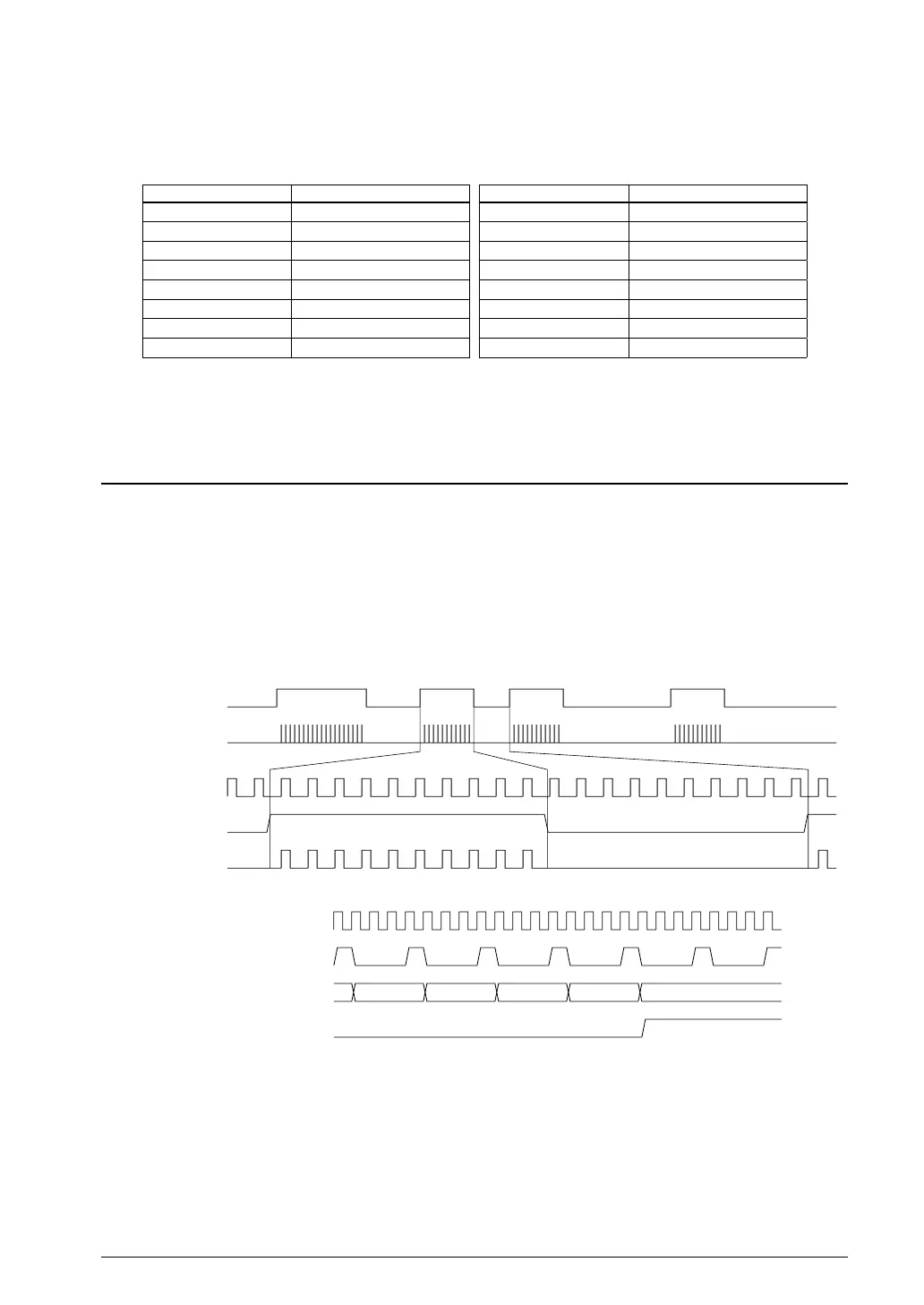
Data transmission control
REMDT
REMO pin output
Carrier
REMDT
REMO pin output
5.1 Data TransmissionFigure 22.
PCLK
Data length counter clock
REMLEN[7:0]
Interrupt signal
4 3 2 1 0
5.2 Underflow Interrupt Generation TimingFigure 22.
(1) Data transmit mode setting
Set REMC to transmit mode by writing 0 to REMMD/REMC_CFG register.
(2) Enabling data transmission
Enable REMC operation by setting REMEN/REMC_CFG register to 1. This initiates REMC transmission.
Set REMDT/REMC_LCNT register to 0 and REMLEN[7:0]/REMC_LCNT register to 0x0 before setting
REMEN to 1 to prevent unnecessar
y data transmission.



 To Next Page