6 INTERRUPT CONTROLLER (ITC)
6-6
Seiko Epson Corporation
S1C17624/604/622/602/621 TECHNICAL MANUAL
NMI6.4
In the S1C17624/604/622/602/621, the watchdog timer can generate a non-maskable interrupt (NMI). The vector
number for NMI is 2, with the vector address set to the vector table's starting address + 8 bytes.
This interrupt takes precedence over other interrupts and is unconditionally accepted by the S1C17 Core.
For detailed information on generating NMI, see the “Watchdog Timer (WDT)” chapt
er.
Software Interrupts6.5
The S1C17 Core provides the “int imm5” and “intl imm5,imm3” instructions allowing the software to gener-
ate any interrupts. The operand imm5 specifies a vector number (0–31) in the vector table. In addition to this, the
intl instruction has the operand imm3 to specify the interrupt level (0–7) to be set to the IL field in the PSR.
The processor performs the same interrupt processing as that of
the hardware interrupt.
HALT and SLEEP Mode Cancellation6.6
HALT and SLEEP modes are cleared by the following signals, which start the CPU.
• Interrupt request signal sent to the CPU from the ITC
• NMI signal output by the watchdog timer
• Debug interrupt signal
• Reset signal
Notes: • If the CPU is able to receive interrupts when HALT or SLEEP mode has been cleared by an
interrupt request for the CPU from
the ITC, processing branches to the interrupt handler rou-
tine immediately after cancellation. In all other cases, the program is executed following the
halt or slp instruction.
• HALT or SLEEP mode clearing due to interrupt requests cannot be masked (prohibited) using
ITC interrupt level settings.
For more information, see “Power Saving by Clock Control” in the appendix chapter. For the oscillator cir
cuit and
system clock statuses after HALT or SLEEP mode is canceled, see the “Clock Generator (CLG)” chapter.
Control Register Details6.7
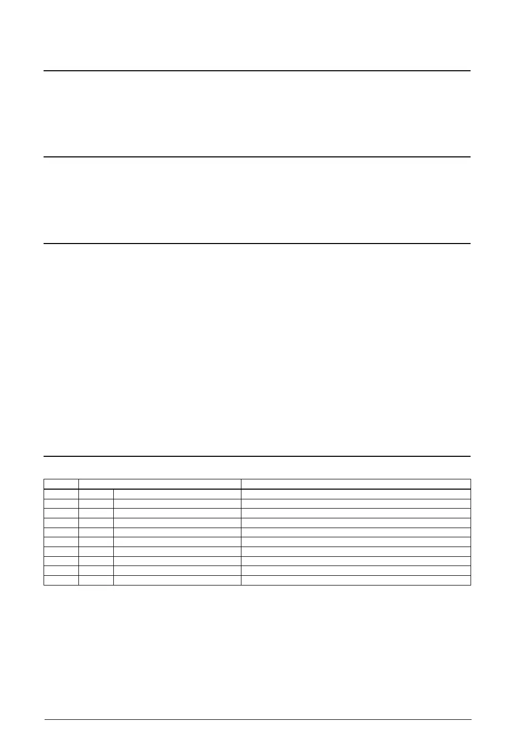
7.1 List of ITC RegistersTable 6.
Address Register name Function
0x4306 ITC_LV0 Interrupt Level Setup Register 0 Sets the P0 and P1 interrupt levels.
0x4308 ITC_LV1 Interrupt Level Setup Register 1 Sets the SWT and CT/RTC interrupt levels.
0x430a ITC_LV2 Interrupt Level Setup Register 2 Sets the T8OSC1 and SVD interrupt levels.
0x430c ITC_LV3 Interrupt Level Setup Register 3 Sets the LCD/T16A2 Ch.0 and T16E Ch.0 interrupt levels.
0x430e ITC_LV4 Interr
upt Level Setup Register 4 Sets the T8F Ch.0&1 and T16 Ch.0 interrupt levels.
0x4310 ITC_LV5 Interrupt Level Setup Register 5 Sets the T16 Ch.1 and T16 Ch.2 interrupt levels.
0x4312 ITC_LV6 Interrupt Level Setup Register 6 Sets the UART Ch.0 and I2CS/UART Ch.1 interrupt levels.
0x4314 ITC_LV7 Interrupt Level Setup Register 7 Sets the SPI Ch.0 and I2CM interrupt levels.
0x4316 ITC_LV8 Interrupt Level Setup Registe
r 8 Sets the REMC and T16A2 Ch.1 interrupt levels.
0x4318 ITC_LV9 Interrupt Level Setup Register 9 Sets the ADC10 and RFC interrupt levels.
The ITC registers are described in detail below. These are 16-bit registers.
Notes: • After the S1C17622 power is turned on, write the specified values to the addresses shown be-
low before executing the interrupt enable (ei) instruction.
1. Address 0x5140 = 0x01 (in 8-bi
t access)
2. Address 0x5141 = 0x06 (in 8-bit access)
• After the S1C17624/604 power is turned on, clear the RTC interrupt flag and then disable RTC
interrupts as shown below before executing the interrupt enable (ei) instruction.
1. RTCIRQ/RTC_INTSTAT register = 1 (clear RTC interrupt flag)
2. RTCIEN/RTC_INTMODE register = 0 (disable RTC interrupt)



 To Next Page