18 UART
S1C17624/604/622/602/621 TECHNICAL MANUAL
Seiko Epson Corporation
18-5
Even when the receive data buffer is full, the shift register can start receiving 8-bit data one more time. An
overrun error will occur if receiving is finished before the receive data buffer has been read. In this case, the
last received data cannot be read. The contents of the receive data buffer must be read out before an overrun
error occurs. For detailed information on overrun errors, refer
to Section 18.6.
The volume of data received can be checked by reading these flags.
The UART allows receive buffer full interrupts to be generated once data has been received in the receive data
buffer. These interrupts can be used to read the receive data buffer. By default, a receive buffer full interrupt
occurs when the receive data buffer receives one 8-bit data (status (2) above). This can be
changed by setting
RBFI/UART_CTLx register to 1 so that an interrupt occurs when the receive data buffer receives two 8-bit data.
Three error flags are also provided in addition to the flags previously mentioned. See Section 18.6 for detailed
information on flags and receive errors.
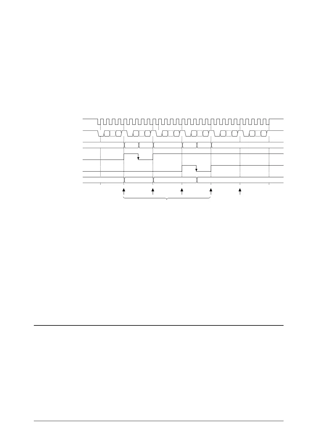
Receive buffer full interrupt request
(RBFI = 0)
Overrun error
interrupt request
Sampling clock (sclk)
SINx
Receive data buffer
RDRY
RD2B
RXD[7:0]
Interrupt
data 1
S1 D0 ··· P S2 S1 D0 ··· P S2 S1 D0 ··· P S2 S1 D0 ··· P S2 S1 D0 ··· P S2 S1 D0 ··· P S2
data 2 data 3 data 4 data 5 data 6
Rd
Rd
data 3, 4data 2data 1 – data 2, 3 data 3
data 3data 2data 1
S1: Start bit, S2: Stop bit, P: Parity bit, Rd: Data read from RXD[7:0]
5.2 Data Receiving Timing ChartFigure 18.
Disabling data transfers
After a data transfer is completed (both transmission and reception), write 0 to RXEN to disable data transfers.
The data being transferred cannot be guaranteed if RXEN is set to 0 while data is being sent or received. Before
setting RXEN to 0, check the data transfer status with software in consideration of the communication proc
edure.
The data transmit status can be checked using the TRBS flag.
Note: Setting RXEN to 0 empties the transmit data buffer, clearing any remaining data. The data being
transferred cannot be guaranteed if RXEN is set to 0 while data is being sent or received.
Make sure that the TDBE flag is 1 and the TRBS and RDRY flags are both 0 before disabling data
transfer.
Receive Errors18.6
Three different receive errors may be detected while receiving data.
Since receive errors are interrupt causes, they can be processed by generating interrupts. For more information on
UART interrupt control, see Section 18.7.
Parity error
If PREN/UART_MODx register has been set to 1 (parity enabled), data received is checked for parity.
Data received in the shift register is checked for parity when sent to the receive
data buffer. The matching is
checked against the PMD/UART_MODx register setting (odd or even parity). If the result is a non-match, a
parity error is issued, and the parity error flag PER/UART_STx register is set to 1. Even if this error occurs, the
data received is sent to the receive data buffer, and the receiving operation continues. However, the received
data cannot be guaranteed if a parity
error occurs. The PER flag is reset to 0 by writing 1.