25 R/F CONVERTER (RFC)
S1C17624/604/622/602/621 TECHNICAL MANUAL
Seiko Epson Corporation
25-11
D2 SSENB: Sensor B Oscillation Control/Status Bit
Controls CR oscillation for sensor B. This bit also indicates the CR oscillation status.
1 (W): Start oscillation
0 (W): Stop oscillation
1 (R): Being oscillated
0 (R): Stopped (default)
Sensor B cannot be used in AC oscillation mode for resistive sensors and DC oscillation mode for ca-
pacitive sensors.
D1 SSENA: Sensor A Oscillation Control/Status Bit
Controls CR oscillation for sensor A. This bit also indicates the CR oscillation status.
1 (W): Start oscillation
0 (W): Stop oscillation
1 (R): Being oscillated
0 (R): Stopped (default)
D0 SREF: Reference Oscillation Control/Status Bit
Controls CR oscillation for the reference element. This bit also indicates the CR oscillation status.
1 (W): Start oscillation
0 (W): Stop oscillation
1 (R): Being oscillated
0 (R): Stopped (default)
Notes: • SREF, SSENA, and SSENB are all ineffective when RFCEN/RFC_CTL register is 0 (converting
operation disabled).
• Writing 1 to SSENB does not start oscillation when SMODE[1:0]/RFC_CTL register is 0x1 (AC
oscillation mode for resistive sensors) or 0x2 (DC oscillation mode for capacitive sensors).
• When writing 1 to SREF, SSENA, or SSENB to start oscillation, be sure to avoid that more
than one bit are set to 1.
• Be sure to reset the interrupt flags in the RFC_IFLG register (EREFIF, ESE
NAIF, ESENBIF,
OVMCIF, and OVTCIF) before starting oscillation using SREF, SSENA, and SSENB.
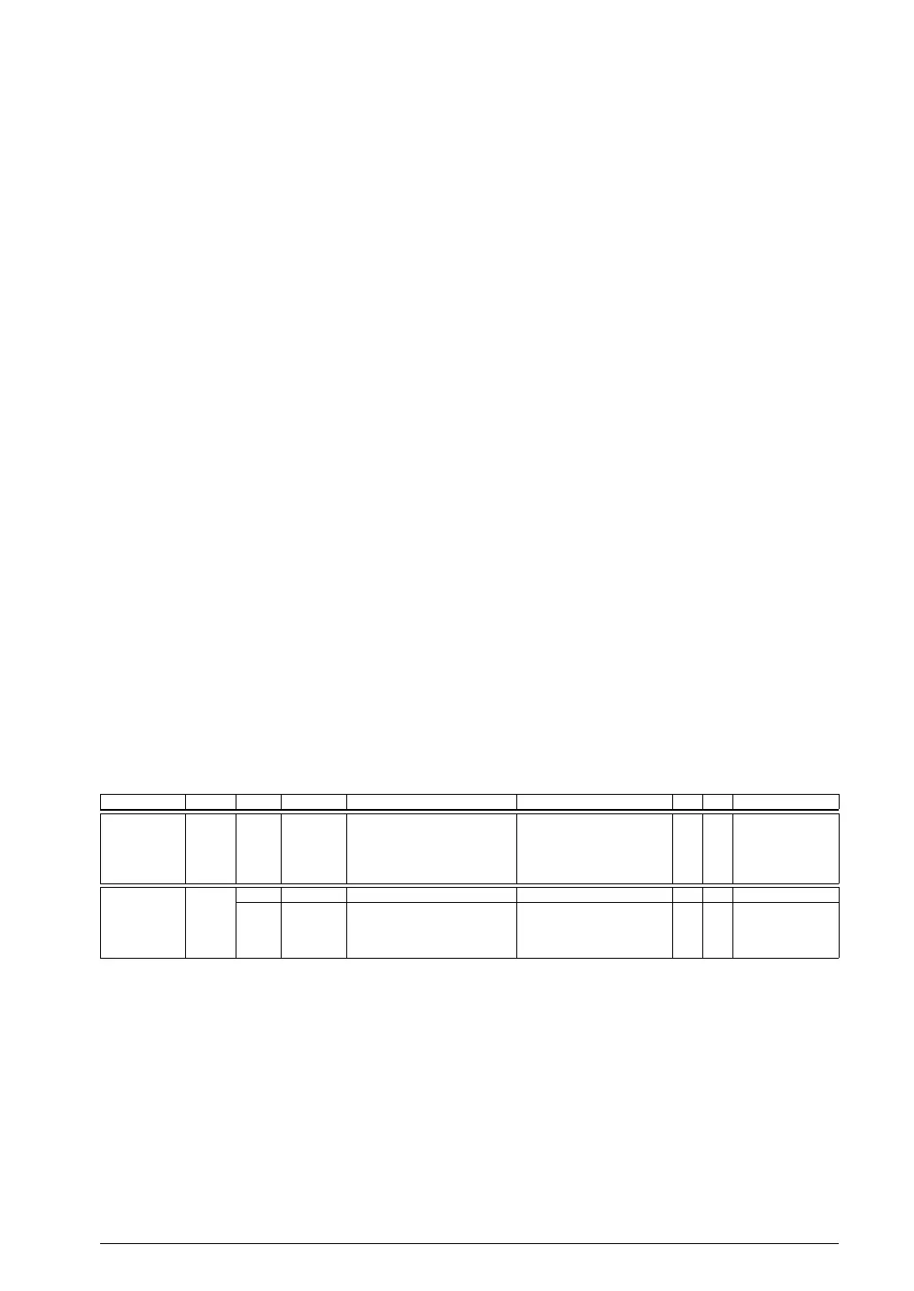
RFC Measurement Counter Low and High Registers (RFC_MCL, RFC_MCH)
Register name Address Bit Name Function Setting Init. R/W Remarks
RFC
Measurement
Counter Low
Register
(RFC_MCL)
0x53a4
(16 bits)
D15–0
MC[15:0]
Measurement counter low-order
16-bit data
0x0–0xffff 0x0 R/W
RFC
Measurement
Counter High
Register
(RFC_MCH)
0x53a6
(16 bits)
D15–8
–
reserved – – – 0 when being read.
D7–0
MC[23:16]
Measurement counter high-order
8-bit data
0x0–0xff 0x0 R/W
D[7:0]/RFC_MCH, D[15:0]/RFC_MCL
MC[23:0]: Measurement Counter Bits
Measurement counter data can be read and written to. (Default: 0x0)
Note: The measurement counter must be set from the low-order value (MC[15:0]/RFC_MCL register)
first. The counter may not be set to the correct value if the high-order value (MC[23:16]/RFC_
MCH register) is written first.



 To Next Page