APPENDIX A LIST OF I/O REGISTERS
S1C17624/604/622/602/621 TECHNICAL MANUAL
Seiko Epson Corporation
AP-A-15
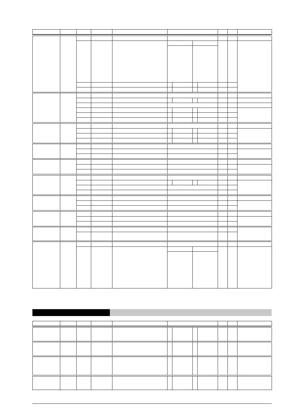
Register name Address Bit Name Function Setting Init. R/W Remarks
RTC Interrupt
Mode Register
(RTC_INTMODE)
0x5141
(8 bits)
D7–5
–
reserved – – – 0 when being read.
D4–2
RTCT[2:0]
RTC interrupt cycle setup RTCT[2:0]
Cycle
X
(0x1)
R/W
0x7
0x6
0x5
0x4
0x3
0x2
0x1
0x0
reserved
1/128 second
1/256 second
1/512 second
1 hour
1 minute
1 second
1/64 second
D1
RTCIMD
RTC interrupt mode select 1 Level sense 0
Edge trigger
X (1) R/W
D0
RTCIEN
RTC interrupt enable 1 Enable 0 Disable X (0) R/W
RTC Control 0
Register
(RTC_CNTL0)
0x5142
(8 bits)
D7–5
–
reserved – – – 0 when being read.
D4
RTC24H
24H/12H mode select 1 24H 0
12H
X (0) R/W
D3
–
reserved – – – 0 when being read.
D2
RTCADJ
30-second adjustment 1 Adjust 0 – X (0) R/W
D1
RTCSTP
Divider run/stop control 1 Stop 0 Run X (0) R/W
D0
RTCRST
Software reset 1 Reset 0 – X (0) R/W
RTC Control 1
Register
(RTC_CNTL1)
0x5143
(8 bits)
D7–3
–
reserved – – – 0 when being read.
D2
RTCRDHLD
Read buffer enable 1 Enable 0
Disable
X (0) R/W
D1
RTCBSY
Counter busy flag 1 Busy 0
R/W possible
X (0) R
D0
RTCHLD
Counter hold control 1 Hold 0 Running X (0) R/W
RTC Second
Register
(RTC_SEC)
0x5144
(8 bits)
D7
–
reserved – – – 0 when being read.
D6–4
RTCSH[2:0]
RTC 10-second counter 0 to 5 X (*) R/W
D3–0
RTCSL[3:0]
RTC 1-second counter 0 to 9 X (*) R/W
RTC Minute
Register
(RTC_MIN)
0x5145
(8 bits)
D7
–
reserved – – – 0 when being read.
D6–4
RTCMIH[2:0]
RTC 10-minute counter 0 to 5 X (*) R/W
D3–0
RTCMIL[3:0]
RTC 1-minute counter 0 to 9 X (*) R/W
RTC Hour
Register
(RTC_HOUR)
0x5146
(8 bits)
D7
–
reserved – – – 0 when being read.
D6
RTCAP
AM/PM indicator 1 PM 0 AM X (*) R/W
D5–4
RTCHH[1:0]
RTC 10-hour counter 0 to 2 or 0 to 1 X (*) R/W
D3–0
RTCHL[3:0]
RTC 1-hour counter 0 to 9 X (*) R/W
RTC Day
Register
(RTC_DAY)
0x5147
(8 bits)
D7–6
–
reserved – – – 0 when being read.
D5–4
RTCDH[1:0]
RTC 10-day counter 0 to 3 X (*) R/W
D3–0
RTCDL[3:0]
RTC 1-day counter 0 to 9 X (*) R/W
RTC Month
Register
(RTC_MONTH)
0x5148
(8 bits)
D7–5
–
reserved – – – 0 when being read.
D4
RTCMOH
RTC 10-month counter 0 to 1 X (*) R/W
D3–0
RTCMOL[3:0]
RTC 1-month counter 0 to 9 X (*) R/W
RTC Year
Register
(RTC_YEAR)
0x5149
(8 bits)
D7–4
RTCYH[3:0]
RTC 10-year counter 0 to 9 X (*) R/W
D3–0
RTCYL[3:0]
RTC 1-year counter 0 to 9 X (*) R/W
RTC Days of
Week Register
(RTC_WEEK)
0x514a
(8 bits)
D7–3
–
reserved – – – 0 when being read.
D2–0
RTCWK[2:0]
RTC days of week counter RTCWK[2:0]
Days of week
X (*) R/W
0x7
0x6
0x5
0x4
0x3
0x2
0x1
0x0
–
Saturday
Friday
Thursday
Wednesday
Tuesday
Monday
Sunday
Init.: ( ) indicates the value set after a software reset (RTCRST → 1 → 0) is performed.
* Software reset (RTCRST → 1 → 0) does not affect the counter values. This register retains the value set before a software reset is
performed.
0x5200–0x52ab P Port & Port MUX
Register name Address Bit Name Function Setting Init. R/W Remarks
P0 Port Input
Data Register
(P0_IN)
0x5200
(8 bits)
D7–0
P0IN[7:0]
P0[7:0] port input data 1 1 (H) 0 0 (L) × R
P0 Port Output
Data Register
(P0_OUT)
0x5201
(8 bits)
D7–0
P0OUT[7:0]
P0[7:0] port output data 1 1 (H) 0 0 (L) 0 R/W
P0 Port
Output Enable
Register
(P0_OEN)
0x5202
(8 bits)
D7–0
P0OEN[7:0]
P0[7:0] port output enable 1 Enable 0 Disable 0 R/W
P0 Port Pull-up
Control Register
(P0_PU)
0x5203
(8 bits)
D7–0
P0PU[7:0]
P0[7:0] port pull-up enable 1 Enable 0 Disable 1
(0xff)
R/W