13 16-BIT PWM TIMERS (T16A2)
13-6
Seiko Epson Corporation
S1C17624/604/622/602/621 TECHNICAL MANUAL
One-shot mode (TRMD = 1)
Setting TRMD to 1 sets the corresponding counter to one-shot mode.
In this mode, the counter stops automatically as soon as the counter is reset or it overflows. The counter should
be set to this mode to set a specific wait time or for pulse width measurement.
The counter is not cleared to 0 after the count operation is completed in one-shot mode. The counter must be
reset
to clear its value to 0. For more information on resetting methods, see Section 13.5.1, “Counter Reset.”
Normal Channel Mode and Multi-Comparator/Capture Mode13.4.3
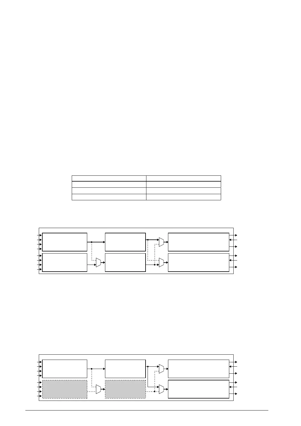
One channel of the T16A2 module basically consists of a counter block and a comparator/capture block. The
T16A2 module also allows the application to use expanded comparator/capture function by connecting two or more
comparator/captur
e blocks to one counter block. To support this expansion, two operating modes are provided:
normal channel mode and multi-comparator/capture mode. This operating mode can be selected using MULTIMD/
T16A_CLK0 register.
Normal channel mode (MULTIMD = 0, default)
Set the T16A2 module to this mode when using it as two channels of different timers by connecting a counter
block with the comparator/capture
block of the same channel. In this mode, the counters can use different count
clocks. Each timer channel provides CCABCNT[1:0]/T16A_CTLx register to select a counter channel to be
connected to the comparator/capture block.
4.3.1 Counter Selection Table 13.
CCABCNT[1:0] Counter channel
0x3, 0x2 Reserved
0x1 Ch.1 (Counter 1)
0x0 Ch.0 (Counter 0)
(Default: 0x0)
When using the T16A2 module in normal channel mode, be sure to connect the counter block to the compara-
tor/capture block in the same channel.
Counter block Ch.0 Comparator/capture block Ch.0
Clock controller Ch.0
Counter block Ch.1 Comparator/capture block Ch.1
Clock controller Ch.1
IOSC
OSC3
OSC1
EXCL5
IOSC
OSC3
OSC1
EXCL6
T16A2
TOUTA6/TOUTB6
CAPA6/CAPB6
Interrupt request
TOUTA5/TOUTB5
CAPA5/CAPB5
Interrupt request
4.3.1 Timer Configuration in Normal Channel Mode Figure 13.
Note: Do not connect a counter block to a comparator/capture block in a different channel in normal
channel mode (MULTIMD = 0), as normal operation cannot be guaranteed.
Multi-comparator/capture mode (MULTIMD = 1)
In order to set three or more comparison values for one counter or to capture the contents of one counter using
three or more trig
ger signals, two or more comparator/capture blocks can be connected to one counter. Multi-
comparator/capture mode is provided for this purpose. In this mode, any counter block can be combined with
the comparator/capture blocks using CCABCNT[1:0] described above. Note, however, that the count clock is
fixed at one type for counter Ch.0, regardless of the counter to be used. The clock settings for o
ther channel are
ineffective.
Counter block Ch.1
Clock controller Ch.1
Counter block Ch.0 Comparator/capture block Ch.0
Clock controller Ch.0
Comparator/capture block Ch.1
IOSC
OSC3
OSC1
EXCL5
IOSC
OSC3
OSC1
EXCL6
T16A2
TOUTA6/TOUTB6
CAPA6/CAPB6
Interrupt request
TOUTA5/TOUTB5
CAPA5/CAPB5
Interrupt request
4.3.2 Timer Configuration in Multi-Comparator/Capture ModeFigure 13.



 To Next Page