7 CLOCK GENERATOR (CLG)
7-8
Seiko Epson Corporation
S1C17624/604/622/602/621 TECHNICAL MANUAL
HSCLK
OSC1
Internal peripheral modules
• 16-bit timer (T16)
• 8-bit timer (T8F)
• UART
• SPI
• I
2
C master (I2CM)
• I
2
C slave (I2CS)
• 16-bit PWM timer (T16E)
• I/O port (P)
• MISC register (MISC)
• Power generator (VD1)
• Supply voltage detector (SVD)
• IR remote controller (REMC)
• A/D converter (ADC10)
• Interrupt controller (ITC)
Gate
On/Off control
PCLK
System clock
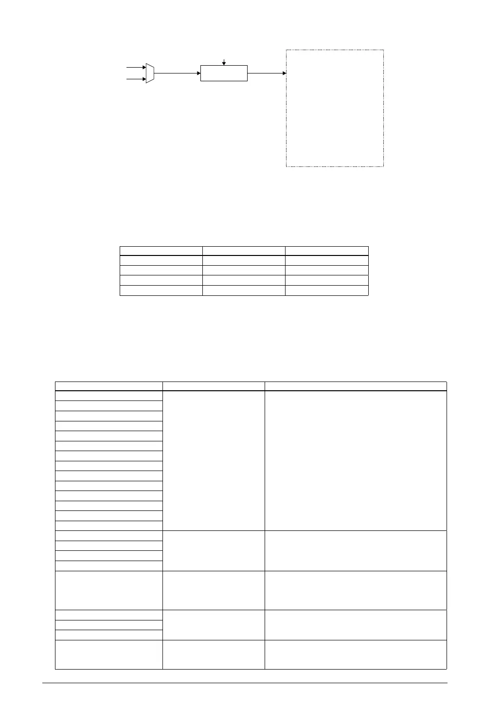
6.1 Peripheral Module Clock Control CircuitFigure 7.
Note: The interrupt controller (ITC) needs PCLK only when the register is set.
Clock supply control
PCLK supply is controlled by PCKEN[1:0]/CLG_PCLK register and PRUN/PSC_CTL register.
6.1 PCLK ControlTable 7.
PCKEN[1:0] PRUN PCLK supply
0x3 1 Enabled (on)
0x2 * Setting prohibited
0x1 * Setting prohibited
0x0 0 Disabled (off)
(Default: PCKEN[1:0] = 0x3, PRUN = 0)
Stop the clock supply to reduce current consumption unless all peripheral modules (modules listed below)
within the internal peripheral circuit area need to be running.
Note: Do not set PCKEN[1:0]/CLG_PCLK register to 0x2 or 0x1 and PRUN/PSC_CTL register to 0,
si
nce doing so will stop the operation of certain peripheral modules.
6.2 Peripheral Modules and Operating ClocksTable 7.
Peripheral modules Operating clock Remarks
16-bit timer (T16) PCLK The PCLK supply cannot be disabled if one or more
peripheral modules in these list must be operated.
The PCLK supply can be disabled if all the periph-
eral circuits in these list can be stopped.
8-bit timer (T8F)
UART
SPI
I
2
C master (I2CM)
I
2
C slave (I2CS)
16-bit PWM timer (T16E)
I/O port (P)
MISC register (MISC)
Power generator (VD1)
Supply volta
ge detector (SVD)
IR remote controller (REMC)
A/D converter (ADC10)
Interrupt controller (ITC) *
Clock timer (CT) OSC1 clock/
divided OSC1 clock
The OSC1 oscillator circuit cannot be disabled if
one or more peripheral modules in these list must
be operated. The PCLK supply can be disabled.
Stopwatch timer (SWT)
Watchdog timer (WDT)
8-bit OSC1 timer (T8OSC1)
Real-time clock (RTC)
(S1C17624/604)
OSC1 clock The O
SC1 oscillator and clock supply to the RTC
can be controlled using RTCCE/RTC_CC register.
The clock supply to the OSC1 peripheral circuits
listed above and PCLK supply can be disabled.
LCD driver (LCD) Clock selected by software
(divided HSCLK clock/
OSC1 clock)
The oscillator circuit used as the clock source can-
not be disabled (see each peripheral module chap-
ter). The PCLK supply can be disabled.
R/
F converter (RFC)
FOUTH/FOUT1 outputs
16-bit PWM timer (T16A2)
(S1C17624/604)
Clock selected by software
(divided IOSC/OSC3/OSC1
clock)
The oscillator circuit used as the clock source cannot
be disabled (see the “16-bit PWM Timers (T16A2)”
chapter). The PCLK supply can be disabled.
* The interrupt controller (ITC) needs PCLK only when the register is set.



 To Next Page