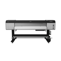
Epson Stylus Pro GS6000 Revision F
DISASSEMBLY & ASSEMBLY Disassembly and Assembly Procedure 121
Confidential
4.4.6.10 SUB_C BOARD ASSY
1. Remove the REAR PAPER GUIDE. (p96)
2. Remove the SPINDLE GUIDE COVER. (p97)
3. Disconnect all the cables and FFCs from the SUB_C BOARD ASSY.
4. Remove the four screws, and remove the SUB_C BOARD ASSY.
A) Silver, Phillips, Cup M3x6: four pieces
Figure 4-78. Removing the SUB_C BOARD ASSY
Figure 4-79. Connector Layout of the SUB_C BOARD ASSY
Connector assignment:
Connector No. Color Destination
J1
Black MAIN BOARD ASSY (CN24)
J2
Black PF ENCODER ASSY
J3
White F COVER SENSOR (left)
J4
Blue MAIN BOARD ASSY (CN64)
J5
Yellow M COVER SENSOR (left)
J6
Red IC COVER SENSOR (left)
J7*
Black Unused
J8
Blue SUB TANK SENSOR
J9
Red SUB TANK SENSOR
J10
Yellow SUB TANK SENSOR
J11
Black SUB TANK SENSOR
J12
White P/S TERM BOARD ASSY (J4)
J13 Gray SUB_B BOARD ASSY (J18)
J14*
Gray Unused
Some connectors are not used for this printer. Make sure not to
confuse them with the correct ones when reassembling.

 Loading...


