ER1 User Guide 10-15
Digital Input/Output Commands
Digital Input/Output Commands
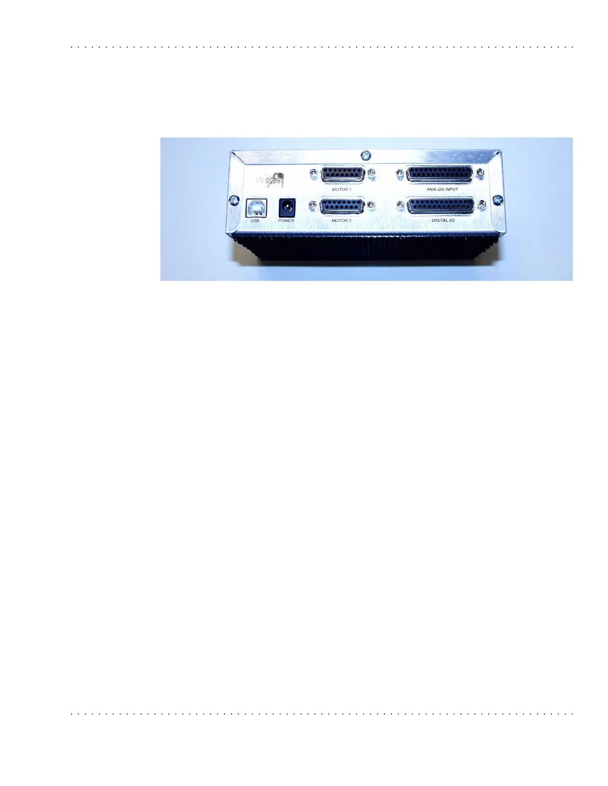
These commands allow accessing of the digital input and output ports of the ER1’s Robot
Control Module and the analog input ports. The pin outs for these ports are in subsequent
sections.
Electrical Characteristics
The following summarizes the electrical characteristics of the ports.
Absolute Maximums
• Maximum input voltage on any pin (digital or analog) 5.3V
• Minimum input voltage on any pin (digital or analog) -0.3V
• Maximum total current sourced from VCC outputs 500mA
Input Logic Thresholds
• For Logic 1: min 2.0V -> max 5.3V
• For Logic 0: min -0.3V -> max 0.8V
Output Logic Thresholds
• For Logic 1: min 2.4V@Io = -300uA
• For Logic 0: max 0.33V@Io = 2mA
• Input Current: min -50uA max 50uA
Analog Input Source Impedance
Analog input source impedance = 9kOhms