ST100A Series Flow Meter INSTALLATION
Fluid Components International LLC 27
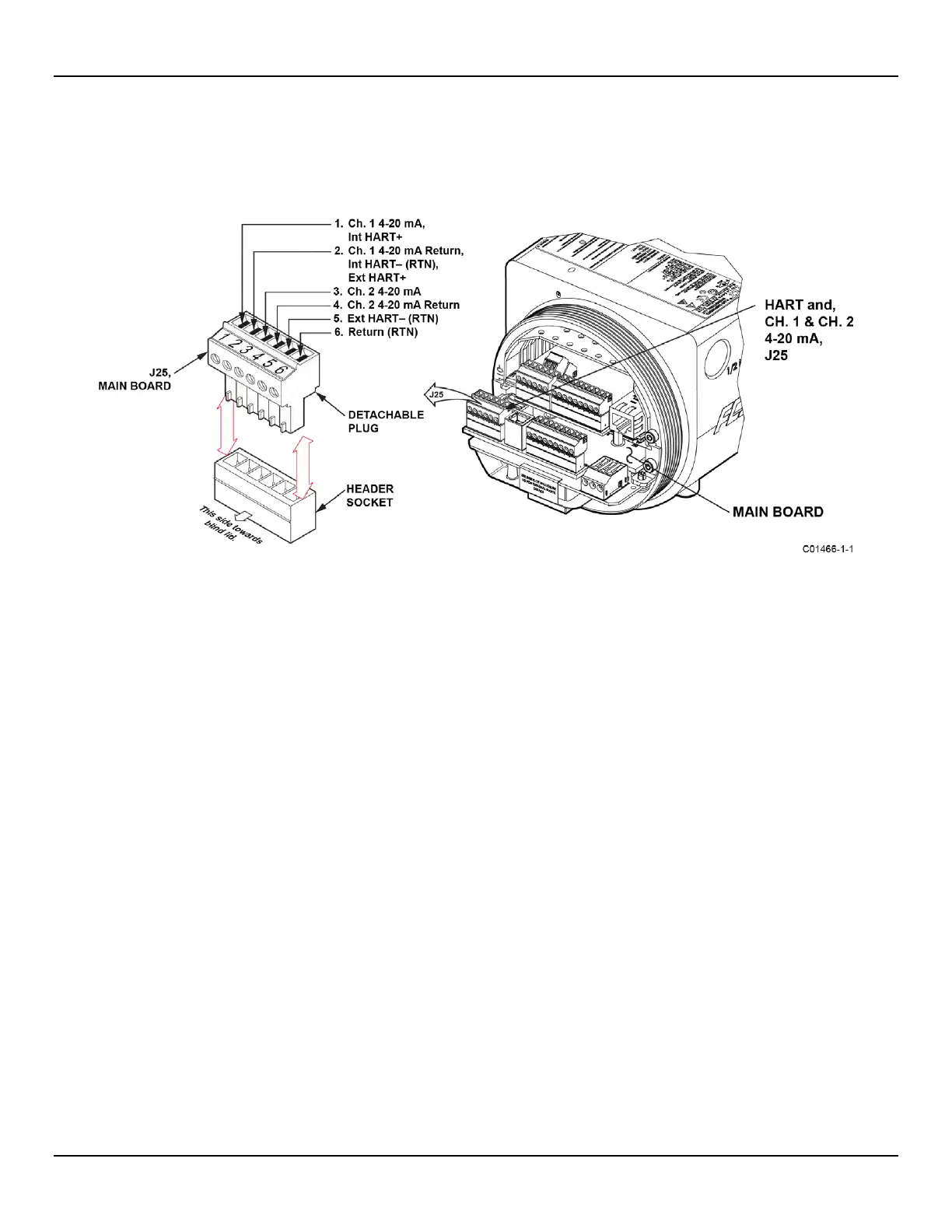
HART Connections
Referencing Figure 22 below, connect the installation HART wiring to the appropriate J25 Phoenix connector terminals depending on the
application. Similar to flow element connector TB1 the J25 connector is a detachable plug that plugs into the header socket on the board.
Use the appropriate J25 connector terminals depending on your application. The connector plug accepts 28-16 AWG (0.14 mm
2
- 1.5
mm
2
) wire.
Figure 22 – HART and Ch. 1 & Ch. 2 4-20 mA Connections, J25
● Single Connection – T
he instrument supplies power to the loop and controls the current as well. For this application connect HART+
to J25-1 (INT HART+) and HART- to J25-2 (CH1/INT HART RTN). This is the default 4-20 mA Ch. 1 output even if HART is not used.
● Network (Multidrop) Connection – The instrument receives loop power from the network, and controls the current. For this
application connect external HART+ to J25-2 (EXT HART+) and external HART- to J25-4 (EXT HART RTN).
The block diagram in Figure 23 below shows the single connection and multidrop HART setups. Use a 250 Ω 1%, ≥ 0.3 W resistor as shown in the
diagram below only if the external HART interface/wiring does not have this resistance built-in (HART requires a minimum loop resistance of 230 Ω).
Cabling Recommendation
Use a shielded, twisted-pair instrument grade wire (min. 24 AWG for runs less than 5000 ft/1500 m; min. 20 AWG for longer distances). The RC
value of the wire (Total Resistance x Total Capacitance) must be less than 65 µs (not a concern for point-to-point topology with a run less than
328 ft/100 m). A cable designed for HART/RS-485 such as Belden 3105A is recommended for complex setups or particularly long runs or both.
The HART communications digital signals are superimposed on top of the channel #1 current loop (4-20 mA) output.
When HART communications is in use, the HART current loop channel #1 MUST be configured as FLOW to comply
with the HART protocol. The channel #1 current loop output is configured as FLOW by default at the factory.

 Loading...


