ST100A Series Flow Meter INSTALLATION
Fluid Components International LLC 31
FOUNDATION Fieldbus/PROFIBUS Configuration
Refer to Figure 18 on page 24. To set J8 for FF/PROFIBUS operation install a 2 mm jumper shunt onto the J12 and J13 jumper pins as
shown in Table 5 below.
Table 5 – FOUNDATION Fieldbus/PROFIBUS Select Jumpers
Install Jumper Shunt over Pins
F
OUNDATION Fieldbus/PROFIBUS Add-On Card Diagnostics/Test
As shown in Figure 18 on page 24 a mini-DIP switch (use push pin or ballpoint pen to actuate) controls the optional Fieldbus/PROFIBUS
add-on card’s #SIM_ENABLE, #NV_ERASE, and #HW_LOCK test signals. This provides a means to activate a “simulate mode” for
Fieldbus conformance testing and for add-on card testing/diagnostics. A particular signal is active when its switch is set to ON. For normal
use all switches are OFF.
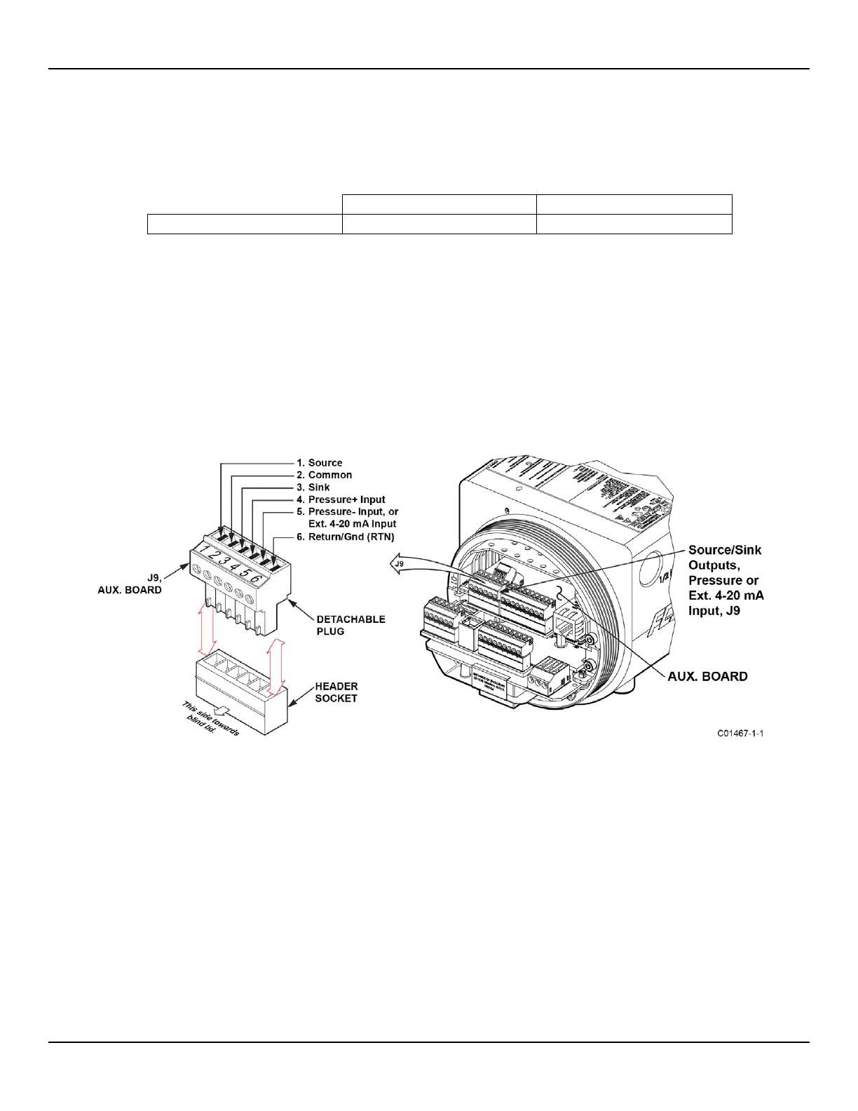
Source/Sink Outputs, Pressure Input, and External 4-20 mA Input J9 Connections
The 6-position terminal strip J9 on the auxiliary board provides connections for the source/sink outputs, pressure input, and the external 4-
20 mA input. Similar to flow element connector TB1 the J9 connector is a detachable plug that plugs into the header socket on the board.
The connector plug accepts 28-16 AWG (0.14 mm
2
- 1.5 mm
2
) wire (refer to Table 2, page 21 for wire size vs. length info). See Figure 28
below. Refer to the paragraphs that follow for J9 connection details.
Figure 28 – Source/Sink Outputs, Pressure Input, and Ext. 4-20 mA Input Connections, J9

 Loading...


