ST100A Series Flow Meter OPERATION
Fluid Components International LLC 53
Analog Output Response to idR Check
During the idR sequence the analog outputs respond as listed below. Readings are taken with a 250 Ω load across Analog Output 1, 2 or 3.
NAMUR Enabled LOW
2.325 Vdc = 23.16 sfps = baseline (example: actual flow output varies from 1-5 volts)
0.900 Vdc = idR In Progress
1.000 Vdc = momentary state
2.326 Vdc = after 3 seconds. idR values are displayed now.
NAMUR Enabled HIGH
2.325 Vdc = 23.16 sfps = baseline (example: actual flow output varies from 1-5 volts)
5.250 Vdc = idR In Progress
1.000 Vdc = momentary state
2.326 Vdc = after 3 seconds. idR values are displayed now.
NAMUR Enabled Disabled
2.325 Vdc = 23.16 sfps = baseline (example: actual flow output varies from 1-5 volts)
1.000 Vdc = idR In Progress
2.326 Vdc = after 3 seconds. idR values are displayed now.
Using Digital Outputs
Digital busses (includes HART, Modbus, and FOUNDATION Fieldbus/PROFIBUS) are mutually exclusive, meaning only one can be active at a
time. When a particular digital output is specified at order time the unit is configured appropriately at the factory. Use the ST100A Series
configuration software (Configuration/Output) to change the digital output selection. Refer to the ST100A Series Configuration Software
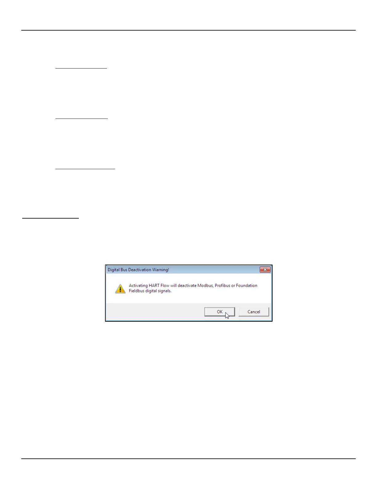
manual 06EN003481 for details. Note that enabling a digital bus will deactivate the other digital bus currently in effect. Figure 55 below shows
an example dialog box produced by the software when the user assigns 4-20 mA #1 to HART Flow with another digital bus already active.
Figure 55 – Digital Bus Deactivation Warning When Enabling HART
F
OUNDATION Fieldbus/PROFIBUS operation requires the optional Fieldbus/PROFIBUS add-on card installed on the main board. Refer to
the F
OUNDATION Fieldbus manual (06EN003482) and PROFIBUS manual (06N003483) for operation details on these digital outputs.

 Loading...


