INSTALLATION ST100A Series Flow Meter
32 Fluid Components International LLC
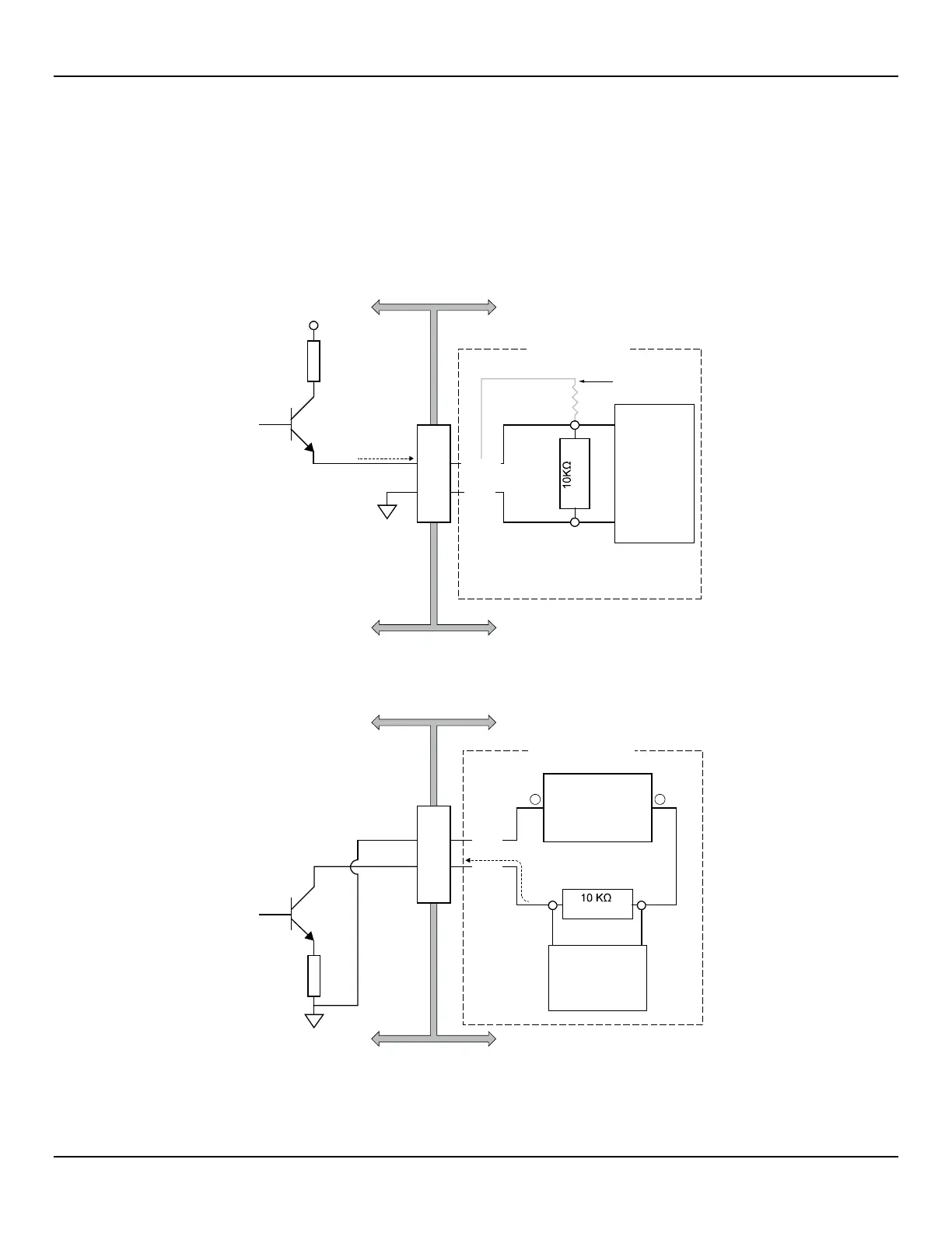
Source/Sink Output Connections
The source/sink outputs are available from the auxiliary board Phoenix connector J9 terminals J9-1 (source), J9-2 (com.), and J9-3 (sink).
Refer to Figure 28.
Wire the terminals as required for your device (using source or sink output as appropriate) as shown in Figure 29 and Figure 30 below. The
source/sink outputs provide a pulse (frequency) output. Observe the output power limits listed below.
● Source Output: 22 ±2 VDC output, 25 mA maximum (supplied by the flow meter)
● Sink Output: 40 VDC maximum, 150 mA maximum (external, user-supplied power source)
Figure 29 – Source Output
J9
(Typical)
External
Device
(Counter, etc.)
24 VDC
25 mA max.
GND
USER WIRING
FLOW METER SIDE USER SIDE
SOURCE
Alternate wiring,
see note below.
Note: Use voltage divider resistor
network if flow meter source voltage
(24 VDC) exceeds your device input.
1
2
C01418-1-1
CURRENT FLOW
Figure 30 – Sink Output
(Typical)
External 24-40 VDC
Power Supply
150 mA max.
External Device
(Counter, etc.)
COM
SINK
USER WIRING
J9
FLOW METER SIDE USER SIDE
2
3
C01417-1-1
CURRENT FLOW
–
+

 Loading...


