ST100A Series Flow Meter OPERATION
Fluid Components International LLC 35
3 OPERATION
Basic Commissioning and Start-Up
Verify the wiring and then apply power to the instrument. LCD-equipped instruments briefly show a welcome screen indicating the
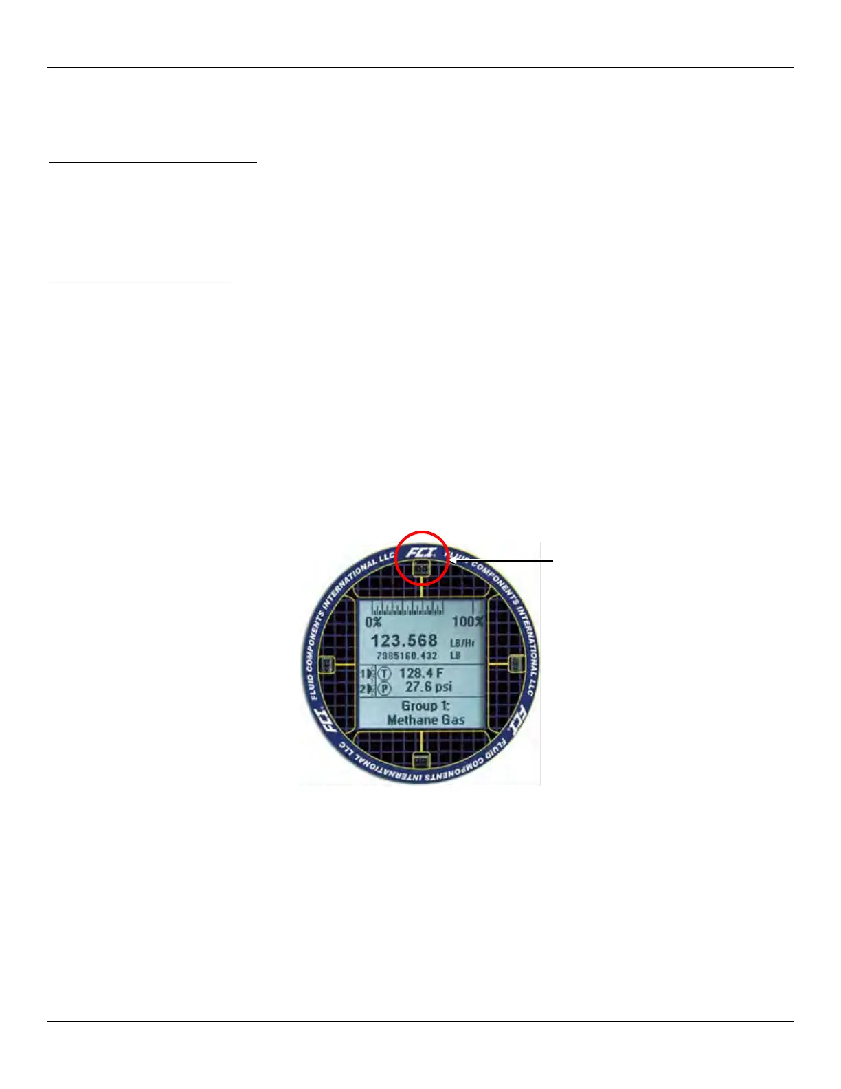
instrument model and core version followed by the normal operation process screen. The normal process screen shows: percentage of
flow bar, icons (if present), process flow rate, totalized flow (optional), temperature in customer units, pressure (optional) in customer units,
calibration group and group name. Once set up there is little need for interaction between the operator and flow meter. Configure the
instrument as necessary using either the HMI interface (option) or the ST100A Series configuration software application.
Configuring the ST100A Series
There are two ways to configure the ST100A Series:
● HMI Front Panel Menu – For instruments with the optional HMI display, access the instrument’s Service menu as described in HMI
Option, Basics below.
● ST100A Series Configuration Software application – The ST100A Series comes with Windows software (PC only) that provides
comprehensive programming of the instrument’s settings. Refer to ST100A Series Configuration Software, page 39.
HMI Option, Basics
The HMI (Human-Machine Interface) option provides the ST100A Series with a built-in setup tool. Four IR (infrared) sensor buttons located
at the 3, 6, 9, and 12 o’clock positions on the display provide access to basic setup parameters. The HMI setup menu can be accessed
through the window without removing the electronics enclosure lids. Enter the HMI setup menu by touching the glass in front of the 12
o’clock sensor (Hot Key) for 3 seconds. The LCD acknowledges the button selection by flashing then inverting the display characters and
background while the button is held.
Figure 32 – Hot Key on the Optional HMI Display
ENTER Setup (hold 3 sec.)

 Loading...


