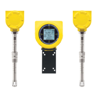
ST100A Series Flow Meter GENERAL
Fluid Components International LLC 1
1 GENERAL
Product Description
The ST100A Series is a thermal dispersion, industrial process grade air/gas flow meter. It is suitable for all air and gas flow measurement
applications in line sizes from 1" to 100" [25 to 2500 mm] and larger. The instrument provides direct mass flow measuring and measures flow rate,
totalized flow and temperature, and the STP versions add pressure measurement.
The measurements are made available to the user by way of 4-20 mA analog output channels with HART or pre-selected digital bus protocols. The
optional graphics display provides real-time process variable values along with flow range and process description information.
There are no moving parts to clean or maintain. A wide selection of process connections are offered to fit with any process piping. Versions are
available for temperature service from -40 °F [-40 °C] to 850 °F [454 °C].
The ST100A Series electronics/transmitter can be integrally mounted with the flow sensor or remote mounted up to 1000' [300m] from the sensor
element. Additional patented or FCI exclusive features include VeriCal® in-situ calibration verification, AST™ (patent pending) adaptive sensing
technology measuring technique, dual sensor/single transmitter models, and a built-in data logger capable of storing more than 20M readings. All
ST100A Series instruments are precision calibrated in FCI’s world-class, NIST traceable calibration facility on one of our flow stands matched to your
gas application and actual installation conditions.
Theory of Operation
The instrument is functionally based on the thermal dispersion operating principal. With AST™, power to the active RTD sensor’s heater is varied to
maintain a constant Delta T with the reference (unheated) RTD sensor. The flow rate and the heater power needed to maintain Delta T is
proportional. Once the heater current reaches a set maximum, the heater current is maintained as the instrument reads the varying sensor
resistance (Delta R). This resistance is proportional to flow rate. The transition between reading the heater power (constant Delta T) and reading the
sensor resistance (constant power) is seamless and automatic and is the key to the AST™ feature. The differential signal, whether it’s from the
sensor heater power (constant Delta T) or the sensor resistance (constant power) is scaled to drive a 4-20 mA flow output. A second temperature
output, from the unheated reference sensor, drives a second 4-20 mA output. A third 4-20 mA output is optional.
Safety Instructions
Explosion Hazard. Do not disconnect equipment when flammable or combustible atmosphere is present.
● Field wiring shall be in accordance with NEC (ANSI-NFPA 70) or CEC (CSA C22.1) locations as applicable.
● The instrument must be installed, commissioned and maintained by qualified personnel trained in process automation and control
instrumentation. The installation personnel must ensure the instrument has been wired correctly according to the applicable wiring diagram.
● All location specific installation and wiring requirements must be met and maintained. FCI recommends an input power circuit breaker
be installed between the power source and the flow meter. This facilitates easy power disconnection during commissioning and
maintenance procedures. Use a switch or circuit breaker if the instrument is in a hazardous area.
● The flow meter contains electrostatic discharge (ESD) sensitive devices. Use standard ESD precautions when handling the circuit
board assemblies.
● Hazardous Areas: The instrument is designed for use in hazardous areas. The approved area classification is identified on the
nameplate along with the temperature and pressure limitations. The USB port and the optional Ethernet port do not support the
hazardous area requirements and should only be used when the area is declassified. Remove any non-certified parts such as plastic
protection caps from cable entry ports and replace by suitable wiring and cabling system certified by notified bodies for use in
hazardous areas.
● When mounting the flow element into the process pipe, it is important that a lubricant/sealant is applied to the mating threads. Use a
lubricant/sealant that is compatible with the process media. Tighten all connections firmly. To avoid leaks do not overtighten or cross-
thread connections.
Order Verification
● Verify the received hardware matches the purchased hardware and application requirements. Verify the model/part number on the
instrument I.D. tag (e.g., ST100AL – 43E8000…) matches the purchased model/part number.
● Review the Calibration requirements as specified on the Engineering Data Sheet in the documentation package. Verify the flow,
temperature and pressure limits meet the application requirements.

 Loading...