OPERATION ST100A Series Flow Meter
50 Fluid Components International LLC
Internal Delta-R Resistor (idR) Check
The Internal Delta-R Resistor (idR) Check is a routine designed to assess the ST100A Series internal normalization. The normalization process fine
tunes the instrument’s ability to accurately measure resistance. Proper normalization also allows FCI electronics to be interchangeable for
replacements, spares or repaired boards. If the unit’s normalization shifts, the accuracy of the meter may be compromised.
By passing the same sensor excitation current used to power the RTDs across three high precision idR resistors (60 Ω, 100 Ω, and 150 Ω) trendng
patterns can be established. Periodically run the idR check to verify proper operation of the ST100A Series electronics. Use the idR check as a
troubleshooting tool to isolate a fault between the sensor and the electronics.
Running the idR Check Using the Optional HMI
Hold the “Hot Key” (top sensor) for three seconds. Select Diagnostics and then Self Test. Select FE 1 IDR (or FE 2 IDR if present) and enter the
User Level Password (E#C). After successful password entry the display shows the FE 1 IDR list again. Select (again) the desired FE. Observe
that Test in Progress displays along with a timer counting down the seconds. See Figure 54, page 52 for the idR test display sequence.
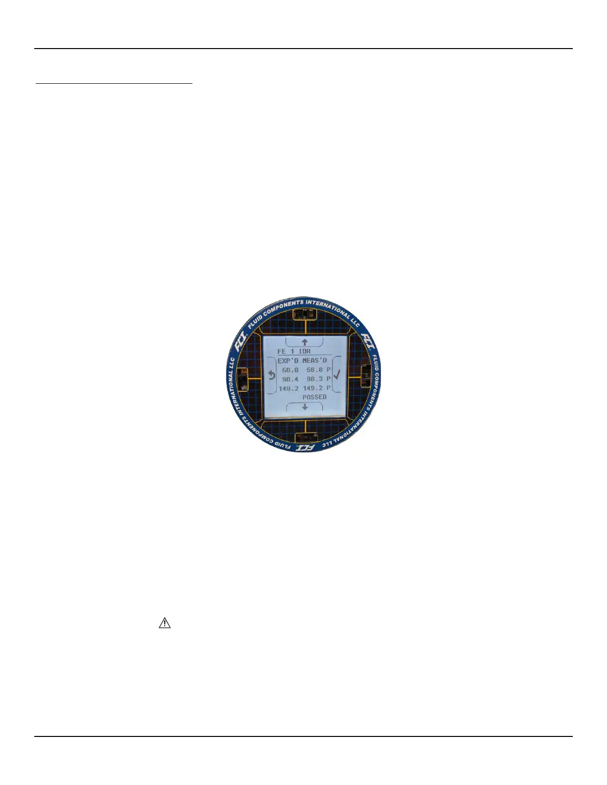
When the idR check completes the expected and measured values for each idR resistor are shown on the HMI display as shown in the
example in Figure 50 below. The left part of the screen shows the expected (EXP'D) values. The right part of the screen shows the
measured (MEAS'D) values. If all three checks pass (“P” shown at the right of all lines), PASSED displays at the bottom. Should any one
of the three checks fail (“F” shown at rightmost part of a line), FAILED displays at the bottom. Data from an HMI-initiated idR check is not
saved; therefore, record the data by hand as required.
Figure 50 – Example idR Check Results Display
Running the idR Check Using the ST100A Configuration Software
Click USB Connect on the home screen. Select the Diagnostics branch from the menu tree on the window's left side. Select the idR
Scheduled Tests tab. Select the “FE #” desired from the Selected FE drop-down list (only FE1 shows for a single-point system). Two
settings that affect scheduled and on-demand idR tests are provided on this screen: FEx Internal Delta-R Pass Fail Criteria, Maximum
Allowed Error (default = 0.5 ohms) and FEx Output Mode During Test, Mode (default = Freeze Flow During Test). Make changes to the
default settings as required for your application.
In the FE1 Schedule Internal Resistor Check field, use the Mode drop-down list to select a schedule mode: Disabled (default), Day of Month
(1-28), Day of Week (0=Sun), or Every(Day). Use the Day, #days, DOW spinner control to define the selected schedule mode. Use the Time
spinner control to enter the desired scheduled check start time. Alternatively, click Run test now on FEx to run the idR check on demand.
Note: When an idR check is started from the configuration software (scheduled or on-demand) the displays shows the Fault
icon ( ) above the flow rate as the check runs. The Fault icon disappears when the idR check completes.
After clicking Run test now on FEx the FEx idR Test Results field displays the expected and the measured resistance values. These
instant checks are not logged to the FRAM and not displayed under the Test Logs tab as the Scheduled Tests files. Furthermore, they
cannot be added to the SD card logs.
For ST100A Series models with FE2 (i.e., dual element) only: Each FE can have its own unique idR Scheduled Tests settings as
shown by the Selected FE drop-down list selection. To make both FEs use the same settings displayed on-screen, tick the Set All FEs to
This Selection checkbox (this checkbox shown only for dual element models such as ST102AA, ST112AA, etc.).

 Loading...


