ST100A Series Flow Meter INSTALLATION
Fluid Components International LLC 25
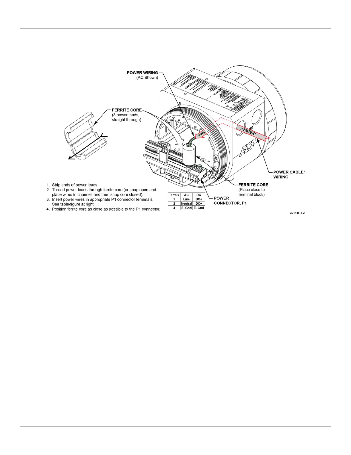
Before connecting the power wires to connector P1, install the ferrite core clamp onto the power wiring as shown in Figure 20 below. Then
insert the stripped power wire ends into the appropriate P1 connector terminals. The ferrite core clamp (supplied with the instrument as
ferrite kit FCI p/n 023638-02) protects the instrument against the adverse effects of EMI/RFI electrical noise.
Figure 20 – ST100A Series Ferrite Core Installation (Auxiliary Board Not Shown for Clarity)
Power overload protection is provided by a clip-mount
ed SMT fuse. Refer to Power Fuse Replacement, page 90 (MAINTENANCE section)
for fuse replacement details.

 Loading...


