INSTALLATION ST100A Series Flow Meter
30 Fluid Components International LLC
Modbus Configuration
Refer to Figure 25 on page 29. To set J8 for Modbus operation install a 2 mm jumper shunt onto the J12 and J13 jumper pins as shown in
Table 3 below.
Table 3 – Modbus Select Jumpers
Install Jumper Shunt over Pins
Note: 1. ● = Jumper Installed
Use the 2 mm line configuration jumpers J9, J10, and J11 as needed for your specific application.
● Termination (End of Line) is typically required for applications with faster data rates or long cable lengths or both. Enable the
instrument’s terminator as required for your application.
● Line biasing is used to ensure that lines are at a known state (noise can cause a false trigger on a floating line). Check first that the
RS-485 network is not already biased before enabling line biasing. Only use one of these jumpers, J9 or J11, not both.
Table 4 below summarizes the line configuration jumper functions.
Table 4 – Modbus Line Configuration Jumpers
F
OUNDATION Fieldbus/PROFIBUS Connections (Option)
Referencing Figure 25 on page 29, connect the F
OUNDATION Fieldbus/PROFIBUS device/network to Phoenix connector J8 on the main
board (not to be confused with the auxiliary board J8 connector that provides the 3
rd
4-20 mA output). Note that the FF/PROFIBUS
connector is also used for the Modbus wiring (only one interface can be active at a time). Connector J8 accepts 24–12 AWG (0.2 mm
2
–
1.5 mm
2
) wire (refer to Table 2, page 21 for wire size vs. length info). It is recommended that wiring have a flammability rating of UL 2556
VW-1 or equivalent.
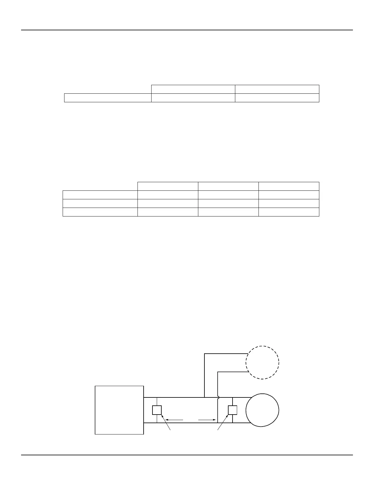
Connect the ST100A Series to a Fieldbus/PROFIBUS device/network as shown in Figure 27 below. Note that devices are connected in
parallel (star fashion).Use a terminator as appropriate for your application. For details on PROFIBUS operation refer to the ST100A Series
PROFIBUS PA manual 06EN003483. For details on F
OUNDATION Fieldbus operation refer to the ST100A Series FOUNDATION Fieldbus
manual 06EN003482.
Foundation Fieldbus/PROFIBUS operation is provided through an optional add-on card that plugs into the ST100A
Series main board.
Figure 27 – Fieldbus/PROFIBUS Wiring
ST100A
Fieldbus/
PROFIBUS
Interface (J8)
Field
Device
Add’l
Field
Device
Wire Pair
FB_A
FB_B
Terminator Terminator
Signals
T
T
C01416-1-1

 Loading...


