OPERATION ST100A Series Flow Meter
40 Fluid Components International LLC
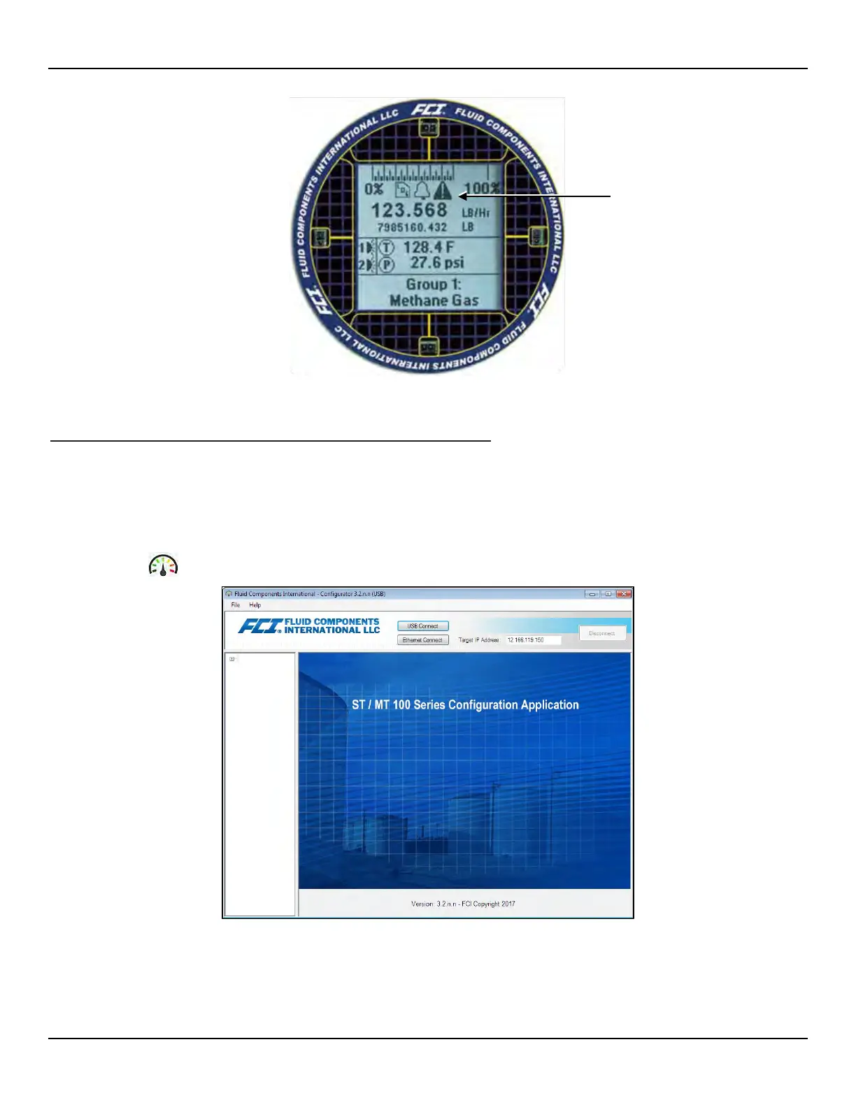
Figure 38 – Example Log, Alarm, and Logging Icons on the Optional Display
ST100A Series Configuration Software Application (User Password: 2772)
The ST100A Series configuration software application provides full access to instrument programming. However, this requires opening the
electronics enclosure and attaching a PC to the onboard USB or Ethernet port. The ST100A Series configuration software application is intuitive,
easy to use and the preferred method for commissioning the instrument.
Use a passive, straight-through USB 2.0 cable with a type-A male connector on one end and a type-B square plug on the other end (as supplied with
the instrument). Connect one end of the USB cable to the computer’s USB port. Connect the other cable end to the ST100A Series’ USB port
(remove blind lid to access USB connector on main board). Launch the application by double clicking the configuration software’s icon on the PC's
Windows desktop: An example of the configurator Welcome screen is shown below.
Figure 39 – The Configurator Welcome Screen
A local USB connection to the PC is the primary communication method—click US
B Connect to activate this connection. Ethernet communication is
an option for remotely connecting a PC using an Ethernet network hub or switch. Figure 40 below shows an example Process Data screen.
Logging, Alarm, and Fault Icons

 Loading...


