ST100A Series Flow Meter INSTALLATION
Fluid Components International LLC 33
External 4-20 mA Input
ST100A Series, except STP model instruments, come with a 4-20 mA input on Phoenix connector J9. Refer to Figure 28. Connect the
external current loop input to J9-5 (IN) and J9-6 (RTN/GND). The 4-20 mA input is used for extended operation mode functions:
● External ST100A Series Flow Input
● External Control Group Switching
Refer to Extended Operation Modes, page 84 (OPERATION section) for extended operation mode details.
Pressure Input (STP1xx Models Only)
The pressure-capable STP model instruments come with a pressure input on Phoenix connector J9. Refer to Figure 28. Connect the
pressure input to J9-4 (+) and J9-5 (-).
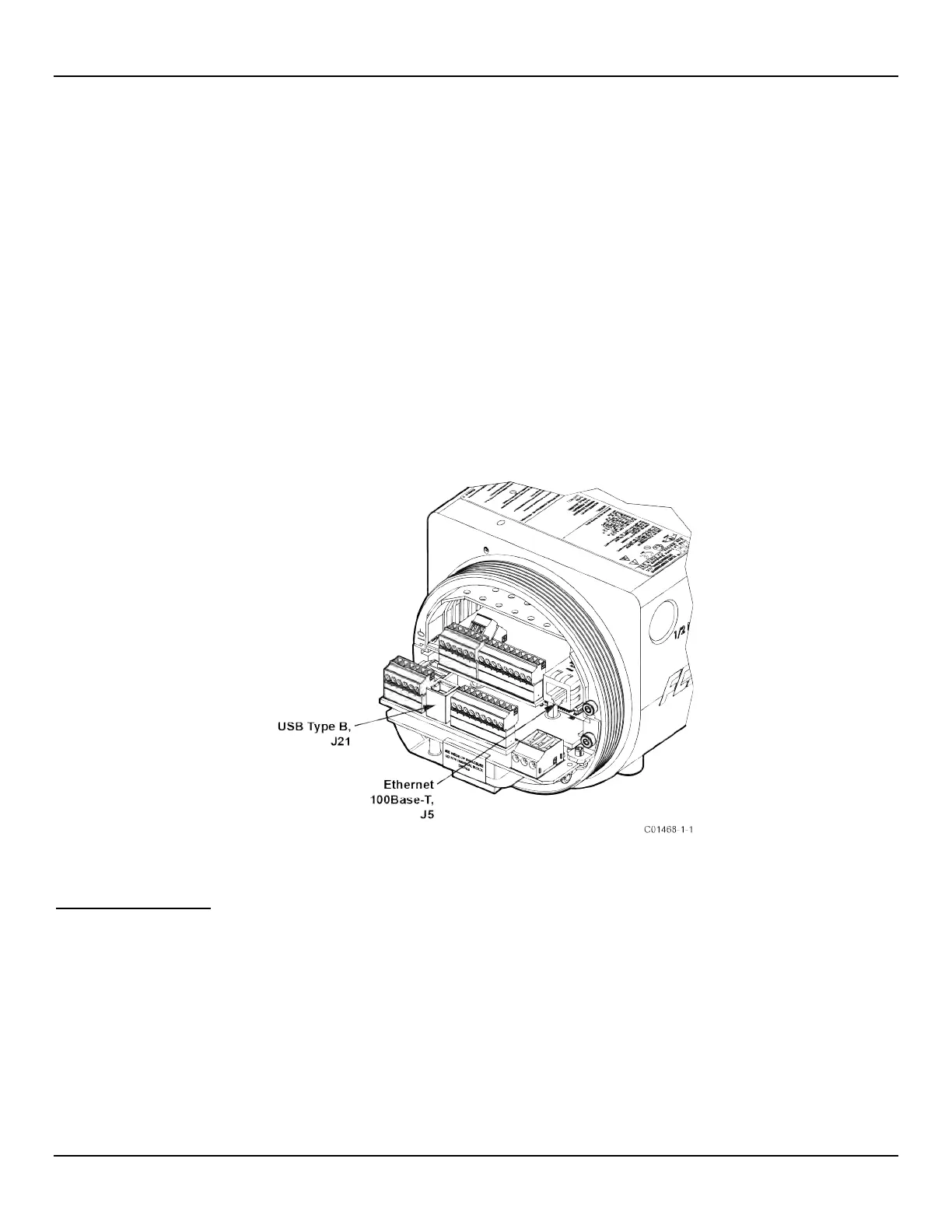
Service Port Connection, USB & Ethernet
The instrument’s service port provides in-depth programming of instrument settings using a PC. See Figure 31 below. For a simple local
service port connection, use the USB port. Refer to Configuring the ST100A Series, page 35 for further information on service port use.
● USB 2.0 – USB Type B connector J21 on the main board (for local connection of PC to the instrument)
● Ethernet (100Base-T/Fast Ethernet) – modular RJ-45 jack J5 on the auxiliary board (for remote connection of PC to the instrument
via an Ethernet network hub or switch)
Figure 31 – ST100A Series Service Ports
Post Installation Check
Verify all wiring connections are secure and correct to the appropriate wiring diagram. Verify the flow direction arrow on the flow element is pointing
in the right direction. Verify the mechanical process connection is secure and meets the system pressure requirements.

 Loading...


