INSTALLATION ST100A Series Flow Meter
24 Fluid Components International LLC
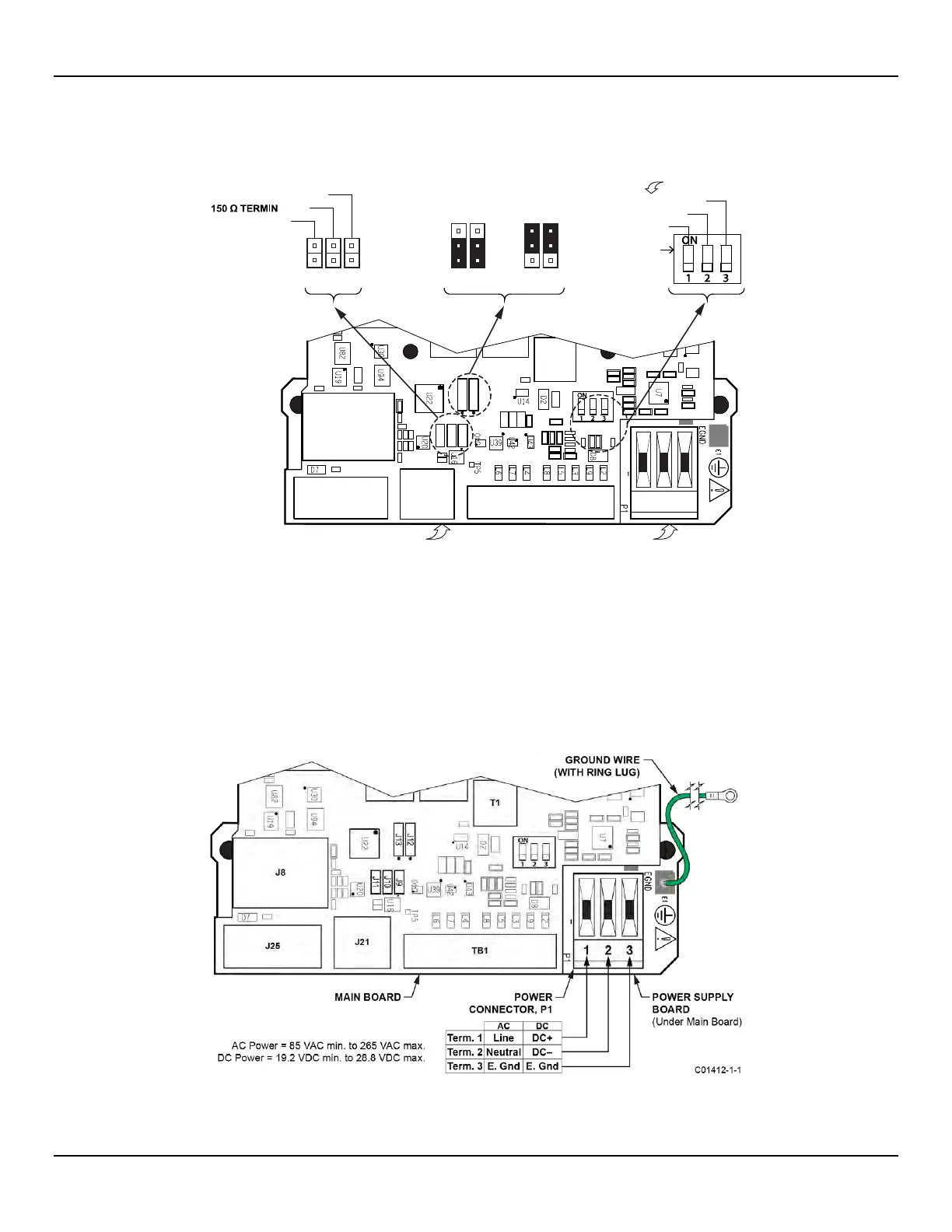
Configuration Jumpers/DIP Switch
When wiring the instrument for Modbus/Fieldbus/PROFIBUS make sure that the instrument is properly configured as shown in Figure 18
below. Refer to Modbus Connections on page 29 and Foundation Fieldbus/PROFIBUS Connections (Option) on page 30 for details.
Figure 18 – Bus Configuration 2 mm Jumper Headers and DIP Switch
C01419-1-1
J9
J12
J13
J10
J11
T1
J8
J25
J21
TB1
J11
J10
J9
J12
J13
J12
J13
MAIN BOARD
MODBUS FF/PROFIBUS
LINE PULLDOWN
LINE PULLUP
#SIM_ENABLE
#NV_ERASE
#HW_LOCK
ATION
POWER SUPP LY BOARD
(Under Main Board)
1
2
3
1
2
3
1
2
3
ON POSITION
ACTIVE WHEN ON
LINE CONFIG. BUS SELECT, J8 FF/PROFIBUSADD-ON CARD
DIAG/TEST
1
2
3
Input Power
Install an AC line disconnect switch with fuse or breaker between the power source and the flow meter.
Always disconnect power before performing maintenance on wiring.
Connect input power to the 3-position Phoenix connector P1 on the power supply board as shown in Figure 19 below. The power
connector accepts 24–12 AWG (0.2 mm
2
– 1.5 mm
2
) wire (refer to Table 2, page 21 for wire size vs. length info). It is recommended that
wiring have a flammability rating of UL 2556 VW-1 or equivalent.
Figure 19 – Input Power Wiring

 Loading...


