ST100A Series Flow Meter INSTALLATION
Fluid Components International LLC 21
Instrument Wiring
The flow transmitter can be powered by 85 – 265 VAC or 24 VDC as specified in the instrument
specification.
The electronics cannot be configured to
switch between AC and DC power. For 220/265 VAC installations, a neutral reference circuit must be used.
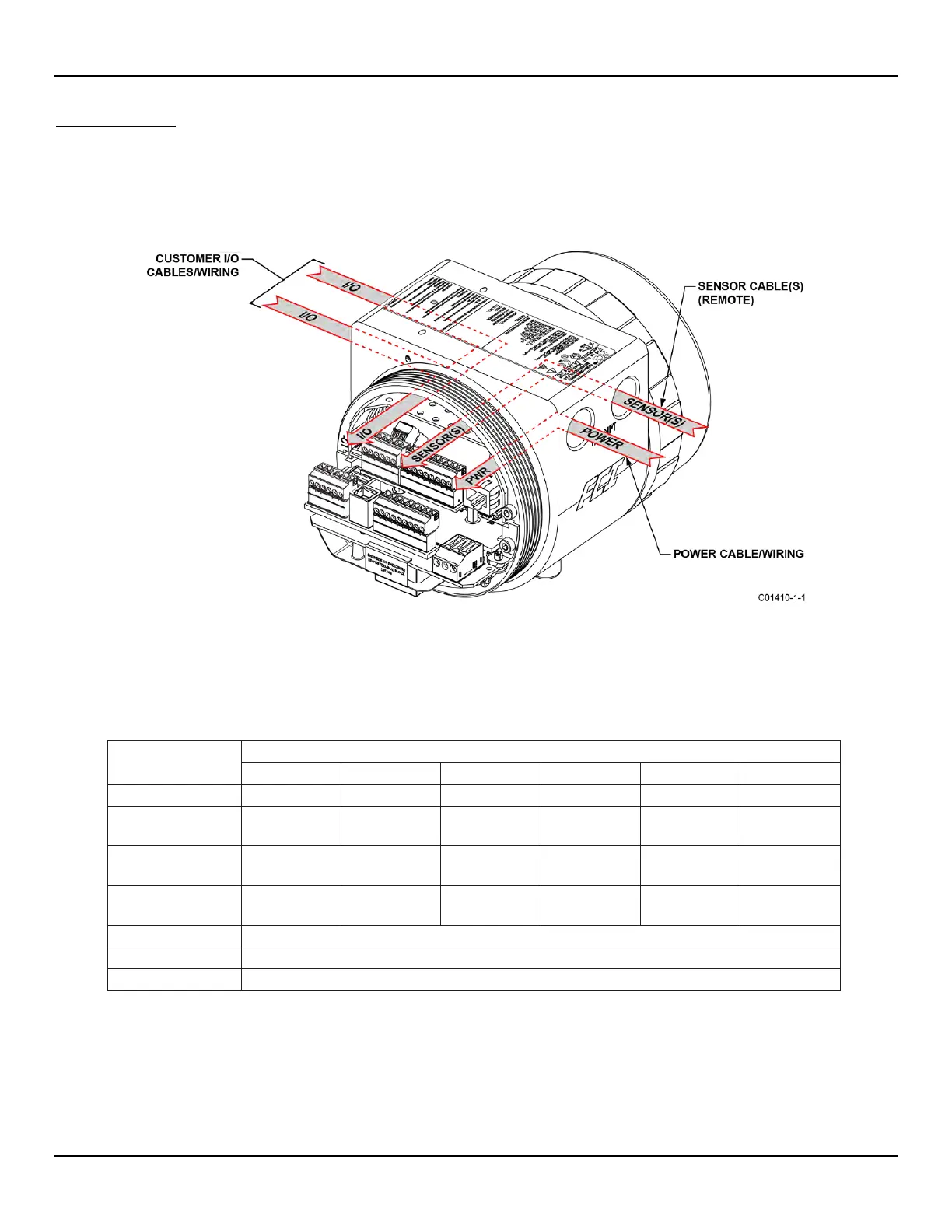
All cable glands and conduit fittings must meet or exceed the area approval rating where the instrument is being installed. The base electronics
enclosure has two wiring ports (1/2" NPT or M20 x 1.5) on both sides of the enclosure body (local enclosure options excluded). The recommended
instrument wiring routing is shown in Figure 15 below.
Figure 15 – Recommended Wiring Routing, Base Electronics Enclosure
Table 2 bel
ow shows the smallest copper wire (maximum AWG number) that can be used for the listed cabling. Contact FCI concerning greater
distances than those listed in the chart. Refer to APPENDIX A, page 105 for additional wiring/cabling information.
Table 2 – Interconnecting Cable Minimum Conductor Size
Connection
Maximum Distance for AWG [mm
2
Flow Element
(8-Cond. Shielded)
24 [0.2047] 24 [0.2047] 24 [0.2047] 22 [0.3255] 22 [0.3255] 18 [0.8230]
STP Flow Element
(10-Cond. Shielded)
22 [0.3255] 22 [0.3255] 22 [0.3255] 22 [0.3255] 22 [0.3255] 18 [0.8230]
Analog Out (HART),
Analog In
RS485 (14-30 AWG) [2.0809-0.0509]
OUNDATION
FF-844 H1 (14-30 AWG) [2.0809-0.0509]
RS485 (14-30 AWG) [2.0809-0.0509]
Notes: 1. Requires a shielded cable. The shield is connected to the GND in the transmitter enclosure. The other end of
the shield is left floating (no connection to the flow element enclosure).
2. Transmission speed determines maximum cable length and vice versa: 9.6 kbps = 3940 ft/1200 m, 19.2 kbps = 3940 ft/
1200 m, 45.45 kbps = 3940 ft/1200 m, 93.75 kbps = 3940 ft/1200 m, 187.5 kbps = 3280 ft/1000 m, 500 kbps = 1310 ft/
400 m, 1500 kbps = 656 ft/200 m, 3000 kbps = 328 ft/100 m, 6000 kbps = 328 ft/100 m, 12000 kbps = 328 ft/100 m.

 Loading...


