ST100A Series Flow Meter INSTALLATION
Fluid Components International LLC 29
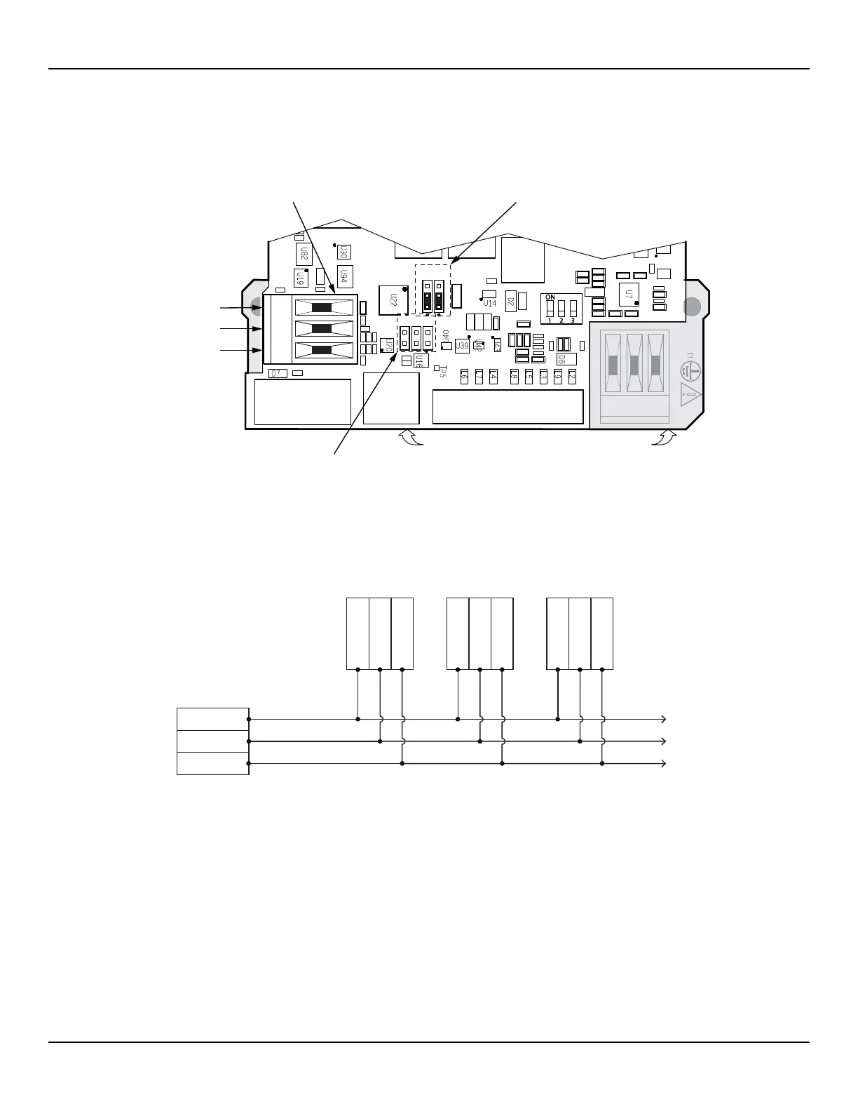
Modbus Connections
Referencing Figure 25 below connect the Modbus device/network to Phoenix connector J8 on the main board (not to be confused with the
auxiliary board J8 connector that provides the 3
rd
4-20 mA output). Note that the J8 connector is also used for FOUNDATION Fieldbus and
PROFIBUS wiring (only one interface can be active at a time). Connector J8 accepts 24–12 AWG (0.2 mm
2
– 1.5 mm
2
) wire (refer to Table
2, page 21 for wire size vs. length info). It is recommended that wiring have a flammability rating of UL 2556 VW-1 or equivalent.
Figure 25 – Modbus/PROFIBUS/Fieldbus Connections, J8
C01531-1-1
1 2 3
J12
J13
J10
T1
1.
2.
3.
B (+),
FIE
LDBUS_A
RETURN
A (–),
FIELDBUS_B
J25
J21
TB1
1 2 3
J11
J9
MAIN BOARD
Modbus/PROFIBUS/Fieldbus
Connector J8
Jumpers J12 & J13 set for
Modbus configuration
(positions 1 & 2)
Line Configuration Jumpers
J9, J10 & J11 (see Table in manual)
POWER SUPP LY BOARD
(Under Main Board)
Connect the ST
100
A Series to a Modbus device/network using a 2-wire RS-485 connection scheme as shown in Figure 26 below. For
details on Modbus operation refer to Modbus Operation, page 77.
Figure 26 – Modbus Wiring
RS-485 MASTER
2-WIRE ONLY DEVICE
DEVICE 1 DEVICE 2 DEVICE 3
One twisted wire pair
plus Gnd/Common.
To remaining
RS-485 Devices
DATA (B)+
DATA (A)-
GND
DATA (B)+
DATA (A)-
GND
DATA (B)+
DATA (A)-
GND
DATA (B)+
DATA (A)-
GND
C01415-1-1

 Loading...


