INSTALLATION ST100A Series Flow Meter
8 Fluid Components International LLC
Compression Fitting
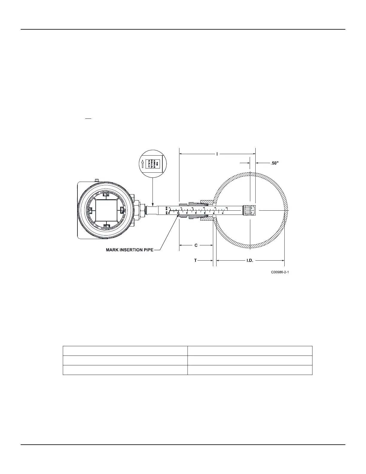
FCI single point insertion flow meters are calibrated at the centerline of the process pipe. The flow element is properly mounted when the
tip of the flow element is located 0.50 inches (13 mm) past the pipe centerline. See Figure 2 below. The scale etched on the side of the
insertion pipe indicates the length to the tip of the flow element. Follow the steps below to install the compression fitting flow element.
1. Calculate the insertion depth using the equation below.
I = Insertion depth
I.D. = Pipe inside diameter
T = Pipe wall thickness
C = Pipe mounting coupling and compression fitting (installed length)
= 0.50" +
..
2
+ +
I = __________
2. Mark the insertion pipe at the calculated insertion depth.
Figure 2 – Compression Fitting Installation, Dimensions
3. Apply proper thread sealant to the tapered pipe thread on the compression fitting and secure into pipe mounting coupling.
4
. Insert the flow element to the insertion depth mark making sure the orientation flat is aligned parallel to the flow direction. Hand tighten
the compression nut. Compression fitting manufacturer recommends 1¼ turns past hand tight.
5. Tighten the compression nut to the torque specified for the corresponding ferrule material. See Table 1 below.
Table 1 – Compression Fitting Material
The metal ferrule configuration can only be tightened one time. Once tightened, the insertion length is no longer adjustable.

 Loading...


