INSTALLATION ST100A Series Flow Meter
14 Fluid Components International LLC
STP100A Flow Element Installation
Model STP100A adds pressure transducer measurements as a third process variable output. The process connections available on the STP model
include the standard ST model connections except the compression fitting. Available process connections include:
● Retractable Packing Gland
● Fixed NPT
● Flanged
All flow element mounting and securing instructions for the selected process connections are identical to the ST100A. These details are provided in
the previous process connection mounting sections.
The pressure limitation for the STP model is determined by the selected pressure transducer. The available options include 50, 160, 500 and 1000
psig (3.44, 11.03, 34.47 and 69.95 bar) maximum pressure ranges.
The pressure transducer is offered in two different temperature service ranges:
● Standard: 32 to 176 °F (0 to 80 °C)
● Explosion Proof (Ex): -22 to 212 °F (-300 to 100 °C)
The pressure transducer is located inside the rectangular shaped enclosure attached to the flow element. The pressure tap is located in the center of
the two thermowells and extends through the center of the insertion pipe into the enclosure where the transducer is located. Because the pressure
transducer is located several feet away from the process media, at the end of a dead head tube assembly, the pressure transducer will be exposed
to the external ambient temperature of the flow element.
Flow Element Wiring
The STP100A can be configured with integral or remote electronics. Wiring diagrams for these
configurations
are located in Appendix A.
Remote
configurations
require a 10-conductor shielded cable as specified in Table 2 on page 21.
ST102AA and ST112AA Flow Element Installation
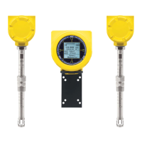
Models ST102AA and ST112AA are dual-element averaging systems operating through a single transmitter. The ST102AA/112AA flow element offers
the same process connections that are available on the basic ST100A. Available process connections include:
● Compression Fitting
● Retractable Packing Gland
● Fixed NPT
● Flanged
All flow element mounting and securing instructions for the selected process connections are identical to the ST100A. These details are provided in
the previous process connection mounting sections. Each flow element is identified with the instrument serial number followed by a -1 or -2.
For example:
Serial no: 409486-1 Description - flow element no. 1
Serial no: 409486-2 Description - flow element no. 2
Installed Insertion Depth, 2-Point System
The flow element point locations for a two-point averaging system (ST102A, ST112A, STP102A, and STP112A) are derived from the US
EPA – Method 1 Traverse Point recommendations. This method is applicable to gas streams flowing in ducts, stacks, and flues with inside
diameters greater than 12 inches. Position the flow element so that the centers of both sensor heads are at a point that is 14.6% of the
pipe’s inside diameter as shown in Figure 8 below.

 Loading...