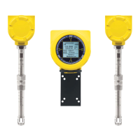
ST100A Series Flow Meter INSTALLATION
Fluid Components International LLC 13
Medium Pressure (max. 500 psig [35 bar(g)]): Loosen the two nuts at the top of the adjustable support rods so that they lie
slightly above the top support beam. Slowly loosen the packing nut until the insertion probe begins to retract. The insertion probe
will come to rest when the support beam at the top of the probe makes contact with the two top adjustable nuts. Continue to
slowly loosen the two top nuts until the insertion probe has fully retracted into the body of the packing gland. If the insertion probe
does not retract when moving the two top nuts, continue loosening the packing nut until retraction resumes. Make sure to move
the two top adjustable nuts at the same time (equally) to prevent the probe from bending and damaging the packing gland. To
lock the probe in a retracted state, tighten the top and bottom adjustable nuts against the top support beam.
c. For ball valve applications: Close the ball valve immediately after retraction to seal off the process. After closing the ball valve it
is then safe to remove the flow element from the back end of the ball valve. If a ball valve is not being used, make sure to
first depressurize the process line before removing the flow element.
2. Flow Element Retraction Using FCI Retractor Tool 026854-01 (Pressure: 500 psig (35 barg) max.)
a. Install the FCI retractor tool to the flow element as described in Insertion/Installation Procedure, page 10, steps ‘a,’ ‘b,’ and ‘c.’
b. Loosen the socket head cap screw on the side of the locking collar. See Figure 7 above.
c. Slowly loosen the packing nut until the load shifts to the top bracket of the retractor tool (approximately 1-1.5 turns).
d. The retractor tool has, on both ends, a 3/8" drive socket that engages the retractor to move the flow element in or out. Use a
hand wrench or a drill to rotate either drive socket in the appropriate direction for retraction as shown in Figure 6. Observe the
Warning below if using an electric drill. Retract the flow element until the sensor head has been fully retracted into the cavity of
the packing gland.
Take note of your environment if using an electric drill to operate the retractor. Do not use an electric drill in an
explosive environment as the drill could create a spark and cause an explosion.
e. Immediately after retraction, close the ball valve to seal off the process.
f. After the ball valve has been closed, it is safe to remove the flow element from the back end of the ball valve.

 Loading...