GE Power Management 745 Transformer Management Relay 5-53
5 SETPOINTS 5.6 S4 ELEMENTS
5
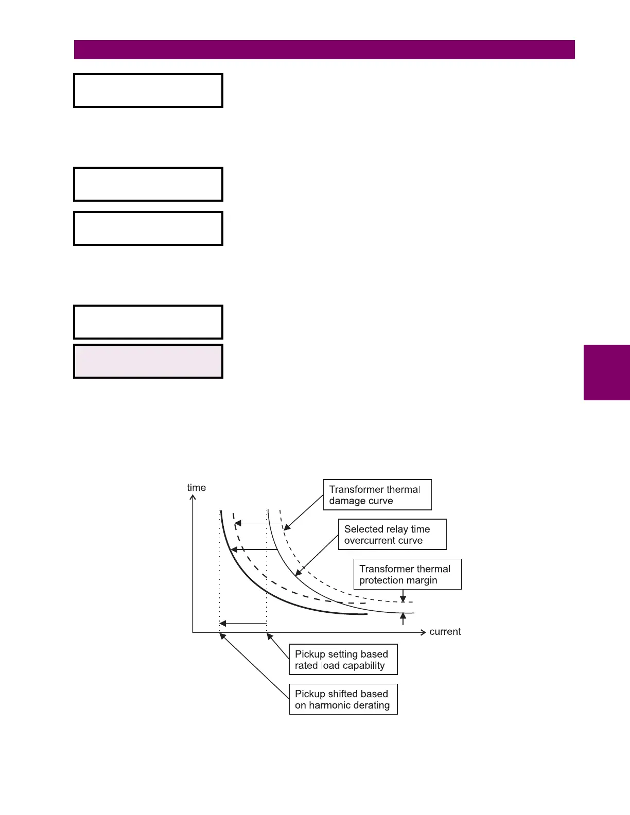
Figure 5–8: HARMONIC DERATING CORRECTION
W1 PHASE TIME OC
SHAPE: Ext Inverse
Range: Ext Inverse / Very Inverse / Norm Inverse / Mod Inverse / Definite
Time / IEC Curve A / IEC Curve B / IEC Curve C / IEC Short Inv /
IAC Ext Inv / IAC Very Inv / IAC Inverse / IAC Short Inv / FlexCurve
A / FlexCurve B / FlexCurve C
Select the time overcurrent curve shape to be used for the W1 (2/3) phase
time overcurrent element. Section 5.9: TIME OVERCURRENT CURVES on
page 5–91 describes the time overcurrent curve shapes.
W1 PHASE TIME OC
MULTIPLIER: 1.00
Range: 0.00 to 100.00 (steps of 0.01)
Enter the multiplier constant by which the selected time overcurrent curve
shape (the base curve) is to be shifted in time.
W1 PHASE TIME OC
RESET: Linear
Range: Instantaneous / Linear
Select
Linear
reset to coordinate with electromechanical time overcurrent
relays, in which the reset characteristic (when the current falls below the
reset threshold before tripping) is proportional to ratio of “energy”
accumulated to that required to trip. Select
Instantaneous
reset to coordinate
with relays, such as most static units, with instantaneous reset
characteristics.
W1 PHASE TIME OC
BLOCK: Disabled
Range: Disabled / Logc Inpt 1 (2-16) /Virt Inpt 1 (2-16) / Output Rly 1 (2-8) /
SelfTest Rly / Virt Outpt 1 (2-5)
W1 HARMONIC DERATING
CORRECTION: Disabled
Range: Disabled / Enabled
Select
Enabled
to enable automatic harmonic derating correction of the W1
(2/3) phase time overcurrent curve. The 745 calculates the derated
transformer capability when supplying non-sinusoidal load currents (as per
ANSI / IEEE C57.110-1986) and, when this feature is enabled, automatically
shifts the phase time overcurrent curve pickup in order to maintain the
required protection margin with respect to the transformer thermal damage
curve, as illustrated below.
 Loading...


