GE Power Management 745 Transformer Management Relay 5-93
5 SETPOINTS 5.9 TIME OVERCURRENT CURVES
5
5.9.3 DEFINITE TIME CURVE
The Definite Time curve shape causes a trip as soon as the pickup level is exceeded for a specified period of
time. The base Definite Time curve has a delay of 0.1 seconds. The curve multiplier makes this delay adjust-
able from 0.000 to 10.000 seconds in steps of 0.001 seconds.
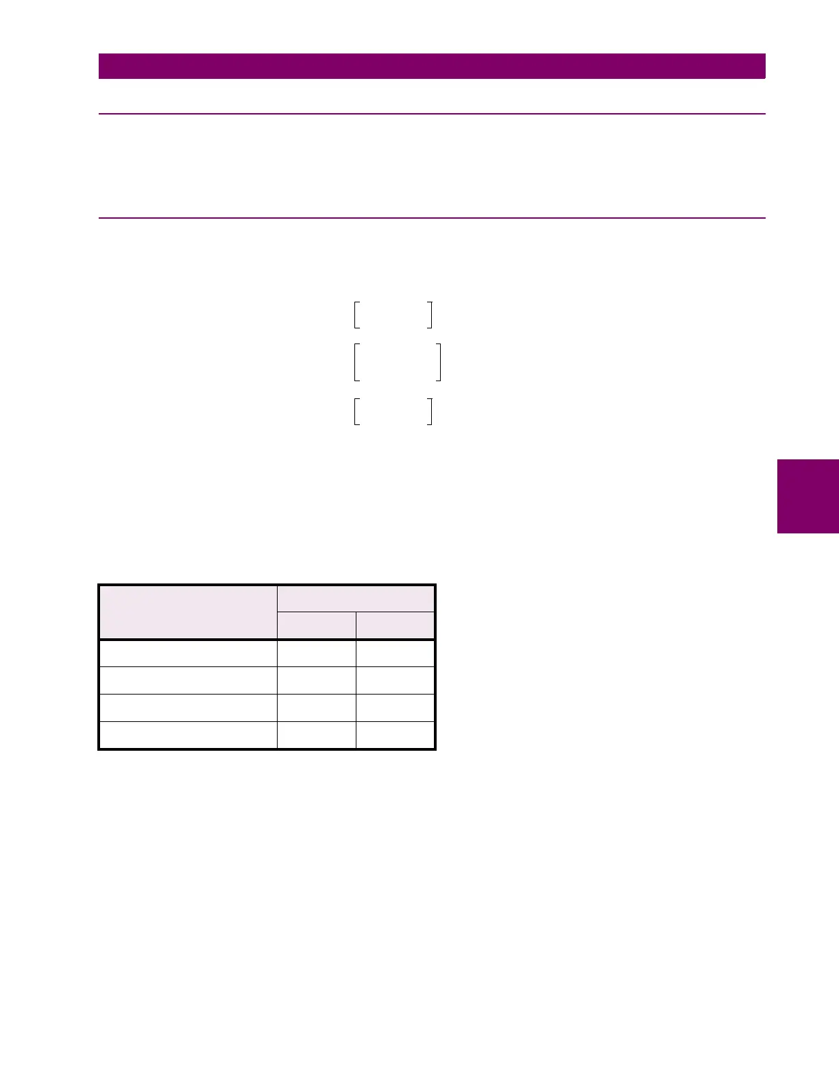
5.9.4 IEC CURVES
For European applications, the relay offers the four standard curves defined in IEC 255-4 and British standard
BS142. These are defined as IEC Curve A, IEC Curve B, IEC Curve C, and Short Inverse. The formula for
these curves is:
where:
T
= Operate Time (seconds)
M
= Multiplier Setpoint
I
= Input Current
I
pkp
= Pickup Current Setpoint
K
,
E
= Constants
Table 5–12: IEC CURVE CONSTANTS
IEC (BS) CURVE SHAPE CONSTANTS
K E
IEC CURVE A (BS142) 0.140 0.020
IEC CURVE B (BS142) 13.500 1.000
IEC CURVE C (BS142) 80.000 2.000
IEC SHORT INVERSE 0.050 0.040
T
M
K
1.03
()
E
1–
-----------------------------
, 1
I
I
pkp
---------
1.03
<≤×
M
K
II
pkp
⁄()
E
1–
--------------------------------
, 1.03
I
I
pkp
---------
20.0
<≤×
M
K
20.0
()
E
1–
-----------------------------
,
I
I
pkp
---------
20.0
≥×
=

 Loading...


