10-18 745 Transformer Management Relay GE Power Management
10.6 PROTECTION SCHEMES 10 COMMISSIONING
10
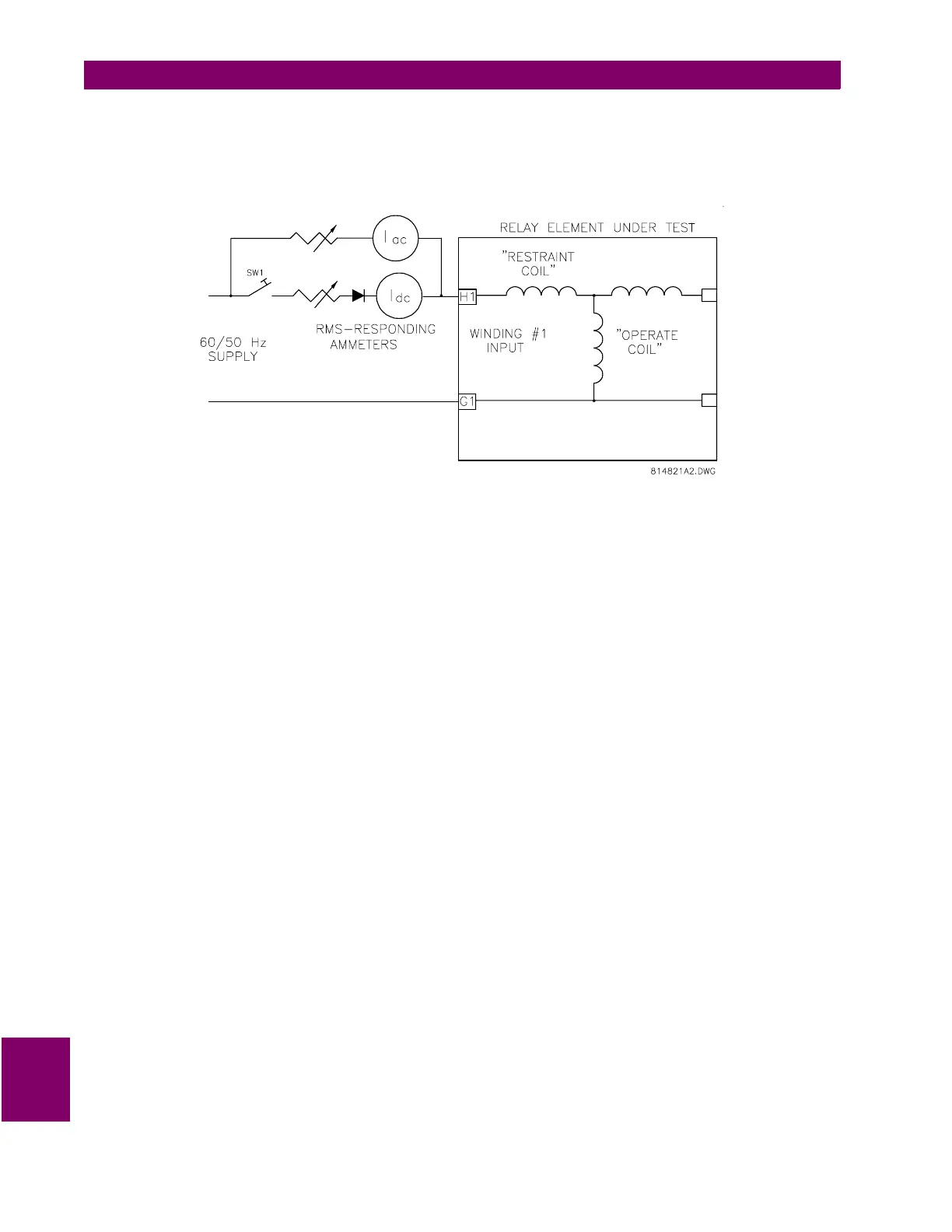
h) 2nd HARMONIC RESTRAINT
To measure the percentage of second harmonic required to block the operation of the harmonic-restraint differ-
ential elements, use the connection diagram shown below. Current is supplied as an operating current to the A-
phase element.
Figure 10–7: 2ND HARMONIC RESTRAINT TEST
1. Close switch S1. Set the AC current,
I
AC
to twice rated CT secondary current. Set
I
DC
to obtain harmonic
content above the 2nd harmonic restraint setting under:
SETPOINTS/S4 ELEMENTS/DIFFERENTIAL/HARMONIC INHIBIT/HARMONIC INHIBIT LEVEL
2. Calculate the percent second harmonic content from the equations below:
If the current is measured with average-responding/reading meters:
b) if the current is measured with rms-responding/reading meters:
3. Open and reclose S1. The relay should not operate.
4. Decrease
I
DC
until the element operates. Calculate the percent of second harmonic at this point using the
equations above. The calculated percent harmonic value should equal the relay setting.
i) 5th HARMONIC RESTRAINT
Verifying the operation of the 5th harmonic restraint requires test equipment capable of generating a current
signal containing a fundamental and 5th harmonic. Most modern dedicated relay test instruments, such as
Powertec's (or Manta) DFR, Doble, or Multiamp instruments are capable of generating appropriate signals. A
power operational amplifier with a suitably rated output, or a power audio amplifier, may also be used to gener-
ate the appropriate signal.
%2nd
100 0.141
I
DC
××
I
DC
0.9
I
AC
×
+
----------------------------------------------
=
%2nd
100 0.141
I
DC
××
I
DC
1.414
I
AC
×
+
----------------------------------------------
=

 Loading...


