GE Power Management 745 Transformer Management Relay 5-71
5 SETPOINTS 5.6 S4 ELEMENTS
5
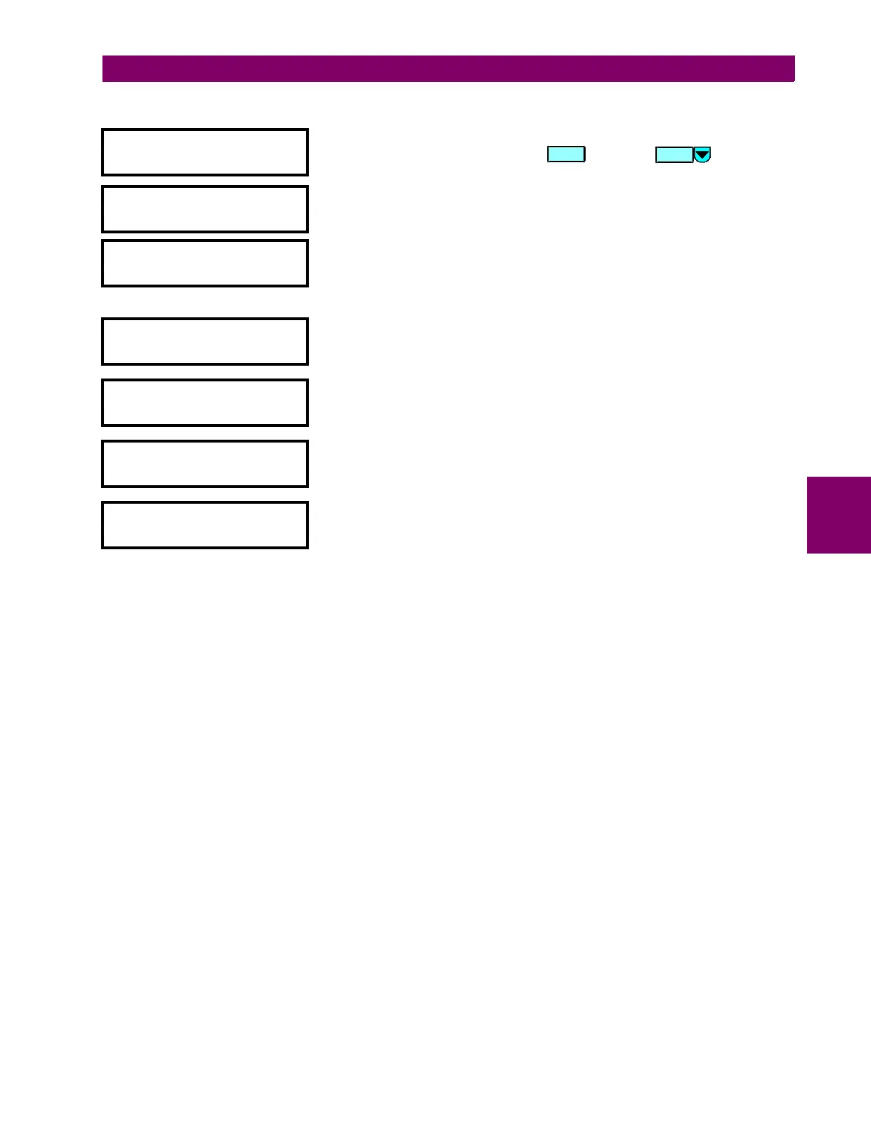
b) WINDING 1 (2/3) HARMONIC DERATING
y W1 HARM DERATING
y
[ENTER] for more
This message indicates the start of the
W1 (2/3) HARMONIC DERATING
section.
To continue these setpoints press or press for the next
section.
W1 HARMONIC DERATING
FUNCTION: Disabled
Range: Disabled / Enabled
W1 HARMONIC DERATING
TARGET: Self-reset
Range: Self-reset / Latched / None
Select
None
to inhibit the display of the target message when the element
operates. Thus an element whose “target type” is
None
will never disable the
LED self-test feature since it cannot generate a displayable target message.
MINIMUM OPERATING
CURRENT: 0.10 x CT
Range: 0.03 to 1.00 (steps of 0.01)
Enter the minimum value of current (in units of relay nominal current)
required to allow the Harmonic Derating element to operate.
W1 HARMONIC DERATING
PICKUP: 0.90
Range: 0.01 to 0.98 (steps of 0.1)
Enter the harmonic derating below which the W1 (2/3) harmonic derating will
pickup and start the delay timer.
W1 HARMONIC DERATING
DELAY: 10 s
Range: 0 to 60000 (steps of 1)
Enter the time that the harmonic derating must remain below the pickup level
before the element operates.
W1 HARMONIC DERATING
BLOCK: Disabled
Range: Disabled / Logc Inpt 1 (2-16) /Virt Inpt 1 (2-16) / Output Rly 1 (2-8) /
SelfTest Rly / Virt Outpt 1 (2-5)
ENTER
MESSAGE

 Loading...


