3-4 745 Transformer Management Relay GE Power Management
3.2 TYPICAL WIRING 3 INSTALLATION
3
3.2 TYPICAL WIRING 3.2.1 DESCRIPTION
Due to the many features built into the 745 relay, a broad range of applications are available to the user. As
such, it is not possible to present connections for all possible schemes. The information in this section will
cover the important aspects of interconnections, in the general areas of instrument transformer inputs, other
inputs, outputs, communications and grounding.
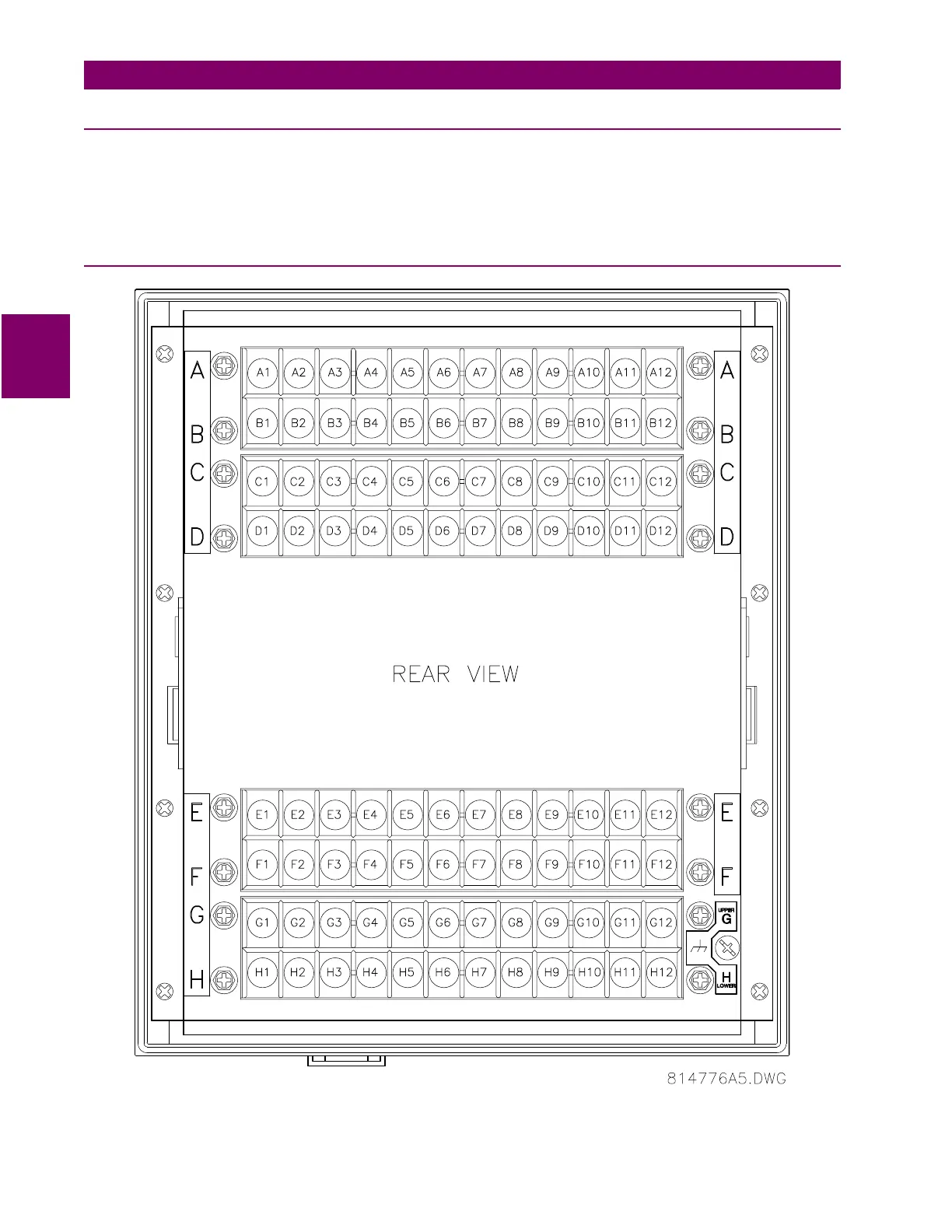
3.2.2 REAR TERMINAL LAYOUT
Figure 3–6: REAR TERMINAL LAYOUT

 Loading...


