GE Power Management 745 Transformer Management Relay 3-1
3 INSTALLATION 3.1 DRAWOUT CASE
3
3 INSTALLATION 3.1 DRAWOUT CASE 3.1.1 CASE DESCRIPTION
The 745 is packaged in the standard SR series arrangement, which consists of a drawout relay and a compan-
ion case. The case provides mechanical protection for the drawout portion, and is used to make permanent
electrical connections to external equipment. Where required, case connectors are fitted with mechanisms,
such as automatic CT shorting, to allow the safe removal of the relay from an energized panel. There are no
electronic components in the case.
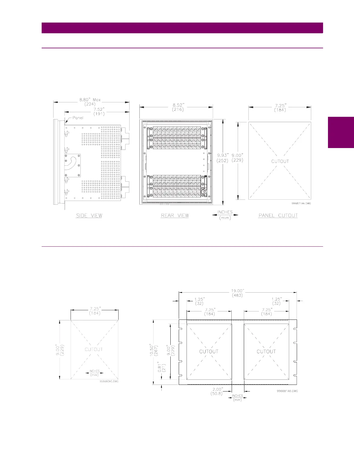
Figure 3–1: CASE DIMENSIONS
3.1.2 PANEL CUTOUT
A 745 can be mounted alone or adjacent to another SR series unit on a standard 19” rack panel. Panel cutout
dimensions for both conditions are as shown. When planning the location of your panel cutout, ensure provi-
sion is made for the front door to swing open without interference to or from adjacent equipment.
Figure 3–2: SINGLE AND DOUBLE SR RELAY PANEL CUTOUT
Single Panel
Double Panel

 Loading...


