10-6 745 Transformer Management Relay GE Power Management
10.4 LOGIC INPUTS & OUTPUT RELAYS 10 COMMISSIONING
10
10.4 LOGIC INPUTS & OUTPUT RELAYS 10.4.1 LOGIC INPUTS
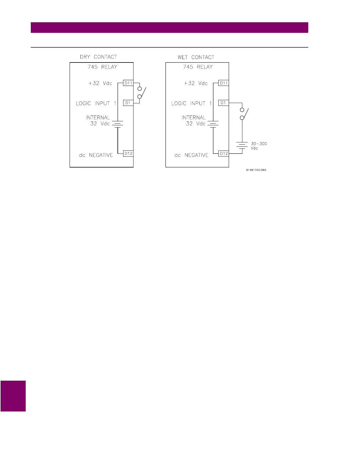
Figure 10–3: LOGIC INPUTS
a) PROCEDURE
1. Prior to energizing any of the Logic Inputs, ensure that doing so will not cause a relay trip signal to be
issued beyond the blocking switches. These should have been opened prior to starting on these tests. If
you wish, you can disable the Logic Input functions by setting:
SETPOINTS/S3 LOGIC INPUTS/LOGIC INPUT 1 (2-16)/LOGIC INPUT 1 FUNCTION:
Disabled
2. Connect a switch between LOGIC INPUT 1 (terminal D1) and +32 V DC (terminal D12), as shown in Fig-
ure 10-3: LOGIC INPUTS (alternatively, use the wet contact approach shown in the same figure). Logic
Inputs can be asserted with either an opened or closed contact, per the user choice. Verify/set the type of
Logic Input to be used with the following setpoint:
SETPOINTS/S3 LOGIC INPUTS/LOGIC INPUTS/LOGIC INPUT 1 (2-16)/INPUT 1 ASSERTED STATE
3. Display the status of the Logic Input using the actual value item:
ACTUAL VALUES/A1 STATUS/LOGIC INPUTS/LOGIC INPUT 1 (2-16) STATE
4. With the switch contact open (or closed), check that the input state is detected and displayed as
Not
Asserted
.
5. Close (open) the switch contacts. Check that the input state is detected and displayed as
Asserted
.
6. Repeat for all the relay logic inputs which are used in your application.

 Loading...


