GE Power Management 745 Transformer Management Relay 3-11
3 INSTALLATION 3.2 TYPICAL WIRING
3
3.2.13 OUTPUT RELAYS
Eight output relays are provided with the 745. Output Relays 2 through 5 have Form A contacts while Output
Relays 6 to 8 and the SELF-TEST relay have Form C contacts. Since Output Relays 2 to 5 are intended for
operating a breaker trip coil, the Form A contacts have higher current ratings than the Form C contacts. Note
that the operating mode of the SELF-TEST relay is fixed, while the other relays can be programmed by the
user via the FlexLogic™ feature.
3.2.14 SOLID STATE TRIP OUTPUT
A high-speed solid state (SCR) output is also provided. This output is intended for applications where it is nec-
essary to key a communications channel.
3.2.15 ANALOG OUTPUTS
The 745 provides 7 analog output channels whose full scale range can be set to one of the following ranges.
0 to 1 mA; 0 to 5 mA; 0 to 10 mA; 0 to 20 mA; 4 to 20 mA
Each analog output channel can be programmed to represent one of the parameters measured by the relay.
For details, see the setpoints chapter.
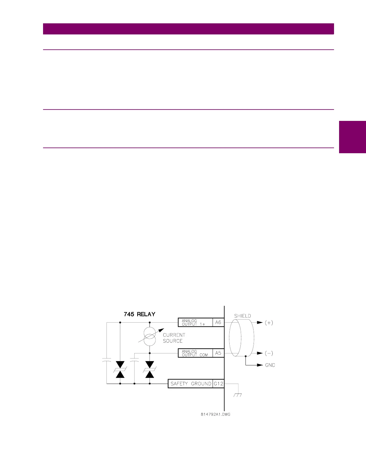
As shown in the typical wiring diagram, the analog output signals originate from terminals A6 to A12 and share
A5 as a common return. Output signals are internally isolated and allow connection to devices which sit at a
different ground potential. Each analog output terminal is clamped to within 36 V of ground. To minimize the
effects of noise, external connections should be made with shielded cable and only one end of the shield
should be grounded.
If a voltage output is required, a burden resistor must be connected at the input of the external measuring
device. Ignoring the input impedance,
R
LOAD
=
V
FULL SCALE
/
I
MAX
.
• If a 5 V full scale output is required with a 0 to 1 mA output channel,
R
LOAD
= 5V / 0.001A = 5 K
Ω
.
• For a 0 to 5 mA channel this resistor would be 1 K
Ω
.
• For a 0 to 10 mA channel, this resistor would be 500
Ω
.
• For a 4 to 20 mA channel this resistor would be 250
Ω
.
Figure 3–12: ANALOG OUTPUT CONNECTION

 Loading...


