GE Power Management 745 Transformer Management Relay 4-1
4 FRONT PANEL OPERATION 4.1 FRONT PANEL
4
4 FRONT PANEL OPERATION 4.1 FRONT PANEL 4.1.1 DESCRIPTION
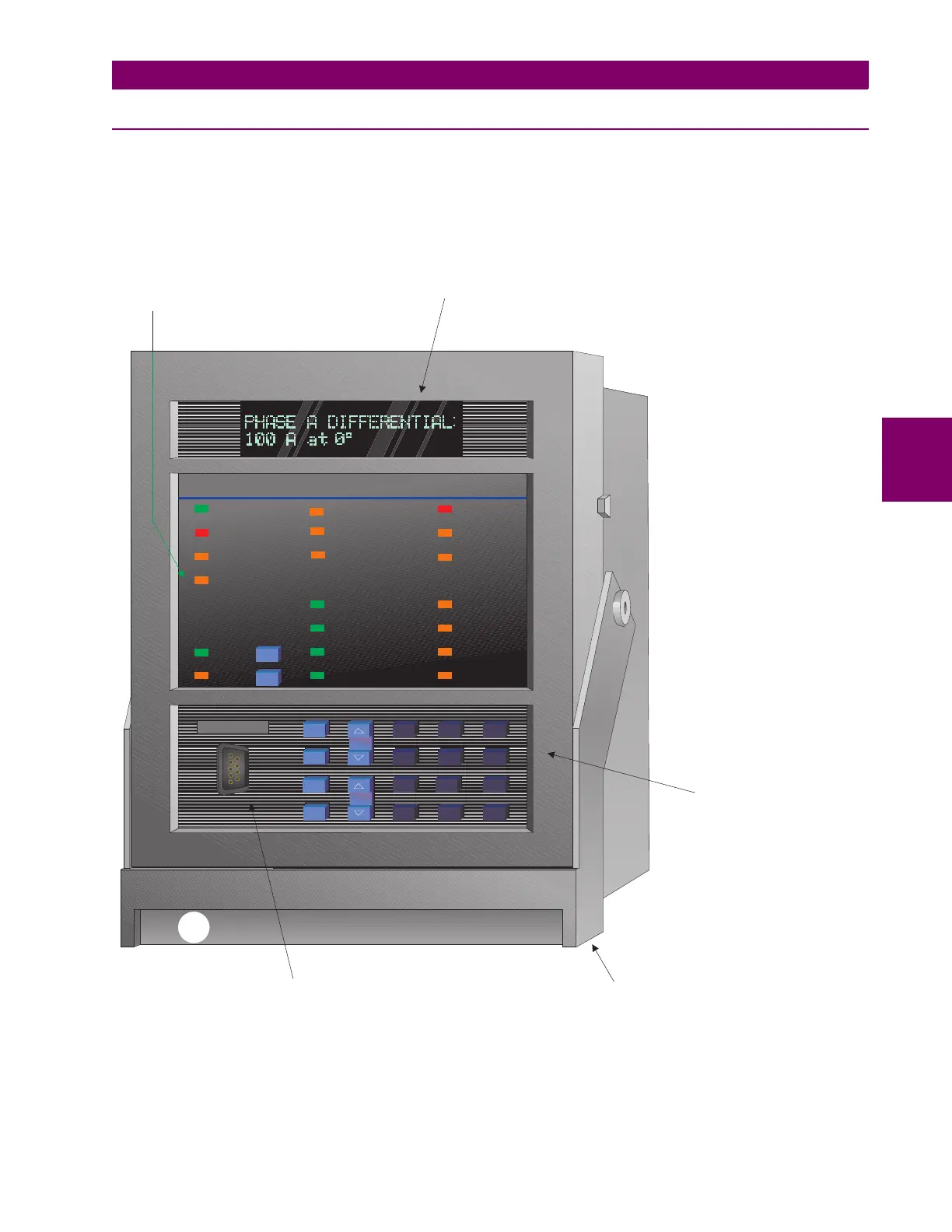
The front panel provides a local operator interface with a vacuum fluorescent display, LED status indicators,
control keys, and program port. The display and status indicators update alarm and status information auto-
matically. The control keys are used to select the appropriate message for entering setpoints or displaying
measured values. The RS232 program port is also provided for connection with a computer running the 745PC
software.
Figure 4–1: 745 FRONT PANEL
745 Transformer Management Relay ™
FrontPanel.CDR
IN SERVICE
LOCAL
SETPOINT GROUP 2
LOAD-LIMIT
REDUCED
TRIP
SELF-TEST
ERROR
SETPOINT GROUP 3
TRANSFORMER
DE-ENERGIZED
ALARM
PICKUP
TEST MODE
TRANSFORMER
OVERLOAD
SETPOINT GROUP 1
PHASE A
PHASE B
PHASE C
GROUNDMESSAGE
PROGRAM PORT
SETPOINT
7 89
4
5
6
12 3
.
0
HELP
MESSAGE
VALUE
ACTUAL
ESCAPE
ENTER
RESET
NEXT
DIFFERENTIAL
BLOCKED
745 STATUS SYSTEM STATUS CONDITIONS
SETPOINT GROUP 4
g
DISPLAY
STATUS INDICATORS AND
LOCAL CONTROL KEYS
SETPOINT ENTRY
AND MONITOR KEYS
HANDLE TO WITHDRAW RELAYPROGRAM PORT INTERFACE
TO LOCAL COMPUTER

 Loading...


