GE Power Management 745 Transformer Management Relay 10-13
10 COMMISSIONING 10.5 DISPLAY, METERING, COMMUNICATIONS, ANALOG OUTPUTS
10
2. Examine the following actual value to verify the programmed temperature:
ACTUAL VALUES A2/METERING/AMBIENT TEMP.
3. Verify that values entered for other months do not affect the value for the present month.
10.5.6 ANALOG OUTPUTS
1. The analog output settings are located in the following setpoints section:
SETPOINTS/S2 SYSTEM SETUP/ANALOG OUTPUTS/...
2. Connect a milliammeter to the Analog Output contacts, COM on A5, A.O. #1 on A6, A.O. #2 on A7, A.O. #3
on A8, A.O. #4 on A9, A.O. #5 on A10, A.O. #6 on A11 or A.O. #7 on A12.
3. From the settings used for the tested Analog output, determine the mA range for the output and the driving
signal and its range for the full range of output current.
4. Apply the input signal and vary its amplitude over the full range and ensure the Analog Output current is
the correct amplitude. Record the results in the table below. Duplicate as required for each Analog Output.
10.5.7 TAP POSITION
1. The Analog Input used to sense tap position is programmed with the following setpoints:
SETPOINTS/S2 SYSTEM SETUP/ONLOAD TAP CHANGER/.....
2. To verify the operation of this circuit, connect a variable resistor across terminals A3 and A4. The resistor
range should cover the full range of resistance produced by the tap changer mechanism. The tap position
is displayed under:
ACTUAL VALUES/A2 METERING/TAP CHANGER/TAP CHANGER POSITION
3. Adjust the resistance to simulate the minimum tap position and verify that a 1 is displayed. Now gradually
increase the resistance up to the value which represents the maximum tap value, verifying that the tap
position indicator tracks the resistance.
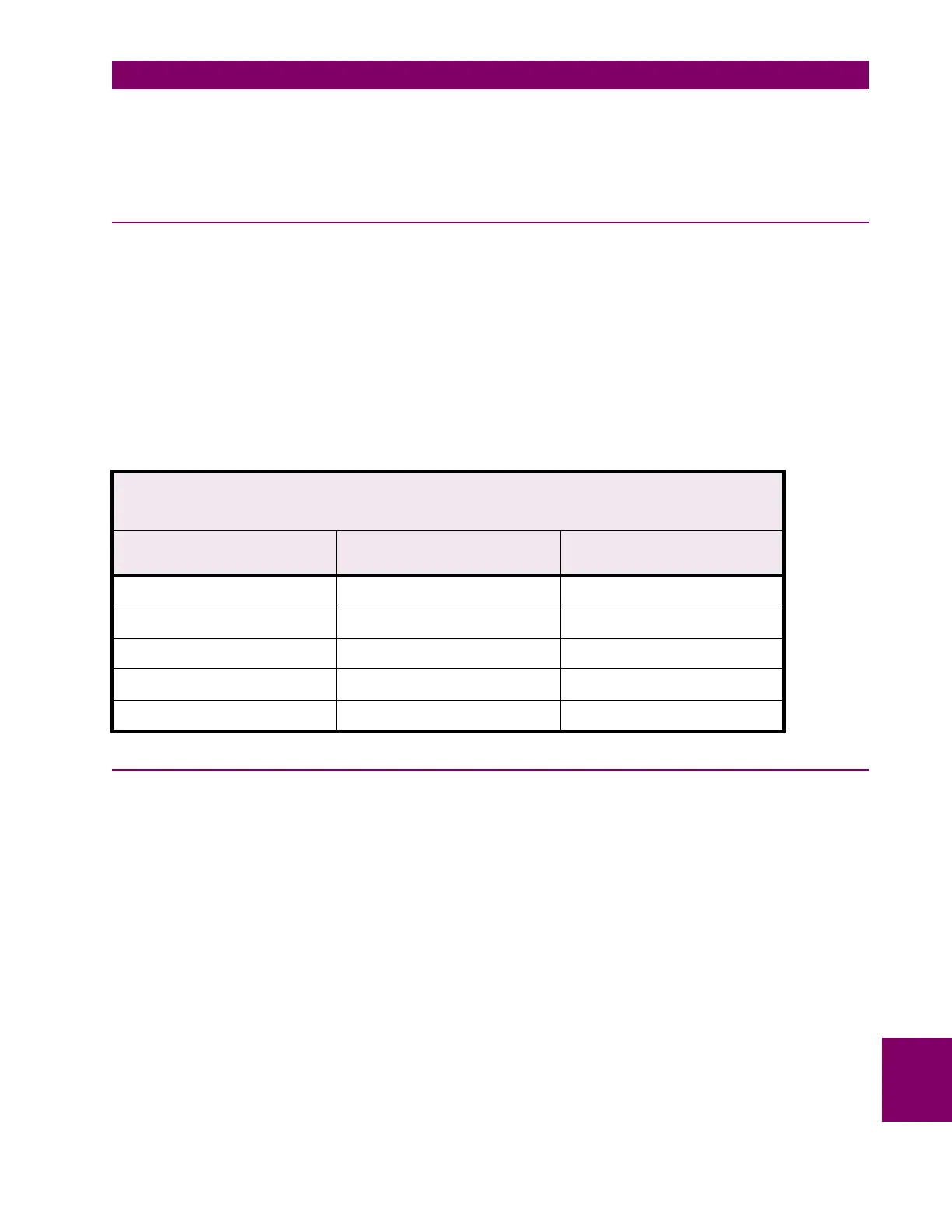
Table 10–4: CALIBRATION RESULTS FOR ANALOG OUTPUTS
Analog Output Number: ______________ Analog Output Min.: ________________
Analog Output Value: ______________ Analog Output Max.: ________________
Analog Output Range: ______________
INPUT SIGNAL AMPLITUDE
(percent of full range)
EXPECTED mA OUTPUT MEASURED mA OUTPUT
0
25
50
75
100

 Loading...


