GE Power Management 745 Transformer Management Relay 5-69
5 SETPOINTS 5.6 S4 ELEMENTS
5
b) VOLTS-PER-HERTZ 1 (2)
y VOLTS-PER-HERTZ 1
y
[ENTER] for more
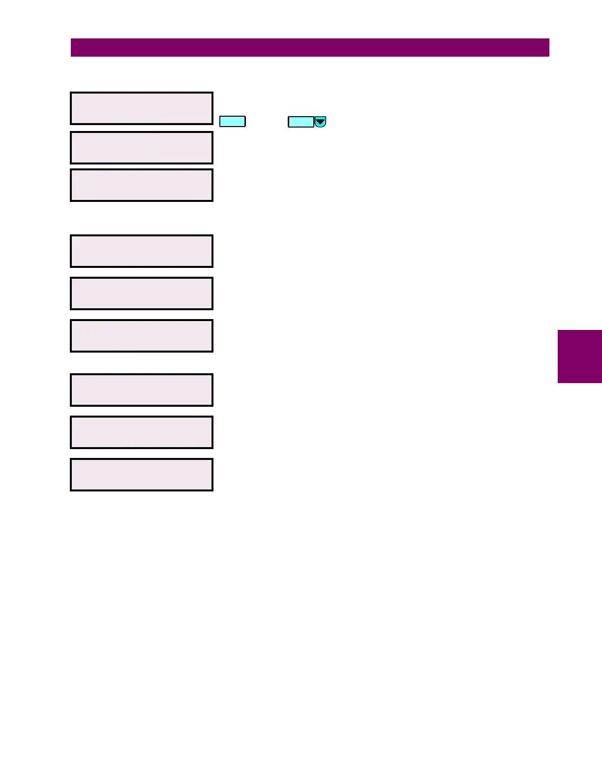
This message indicates the start of the section describing the characteristics
of the
VOLTS-PER-HERTZ 1(2)
element. To continue these setpoints press
or press for the next section.
VOLTS-PER-HERTZ 1
FUNCTION: Disabled
Range: Disabled / Enabled
VOLTS-PER-HERTZ 1
TARGET: Self-reset
Range: Self-reset / Latched / None
Select
None
to inhibit the display of the target message when the element
operates. Thus an element whose “target type” is
None
will never disable the
LED self-test feature because can not generate a displayable target
message.
MINIMUM OPERATING
VOLTAGE: 0.10 x VT
Range: 0.10 to 0.99 (steps of 0.01)
Enter the minimum value of voltage (in terms of nominal VT secondary
voltage) required to allow the volts-per-hertz 1 element to operate.
VOLTS-PER-HERTZ 1
PICKUP: 2.36 V/Hz
Range: 1.00 to 4.00 (steps of 0.01)
Enter the volts-per-hertz value (in V/Hz) above which the volts-per-hertz 1
element will pickup and start the delay timer.
VOLTS-PER-HERTZ 1
SHAPE: Definite Time
Range: Definite Time / Inv Curve 1 / Inv Curve 2 / Inv Curve 3
Select the curve shape to be used for the volts-per-hertz 1 (2) element. A
description of inverse volts-per-hertz curve shapes can be found at the end
of this chapter.
VOLTS-PER-HERTZ 1
DELAY: 2.00 s
Range: 0.00 to 600.00 (steps of 0.01)
Enter the time that the volts-per-hertz value must remain above the pickup
level before the element operates.
VOLTS-PER-HERTZ 1
RESET: 0.0 s
Range: 0.0 to 6000.0 (steps of 0.01)
Enter the time that the volts-per-hertz value must remain below the pickup
level before the element resets.
VOLTS-PER-HERTZ 1
BLOCK: Disabled
Range: Disabled / Logc Inpt 1 (2-16) /Virt Inpt 1 (2-16) / Output Rly 1 (2-8) /
SelfTest Rly / Virt Outpt 1 (2-5)
ENTER
MESSAGE

 Loading...


