5-84 745 Transformer Management Relay GE Power Management
5.7 S5 OUTPUTS 5 SETPOINTS
5
5.7.4 OUTPUT RELAYS
This section contains the settings (including the FlexLogic™ equation) to configure output relays 1 to 8.
y OUTPUT RELAYS
y
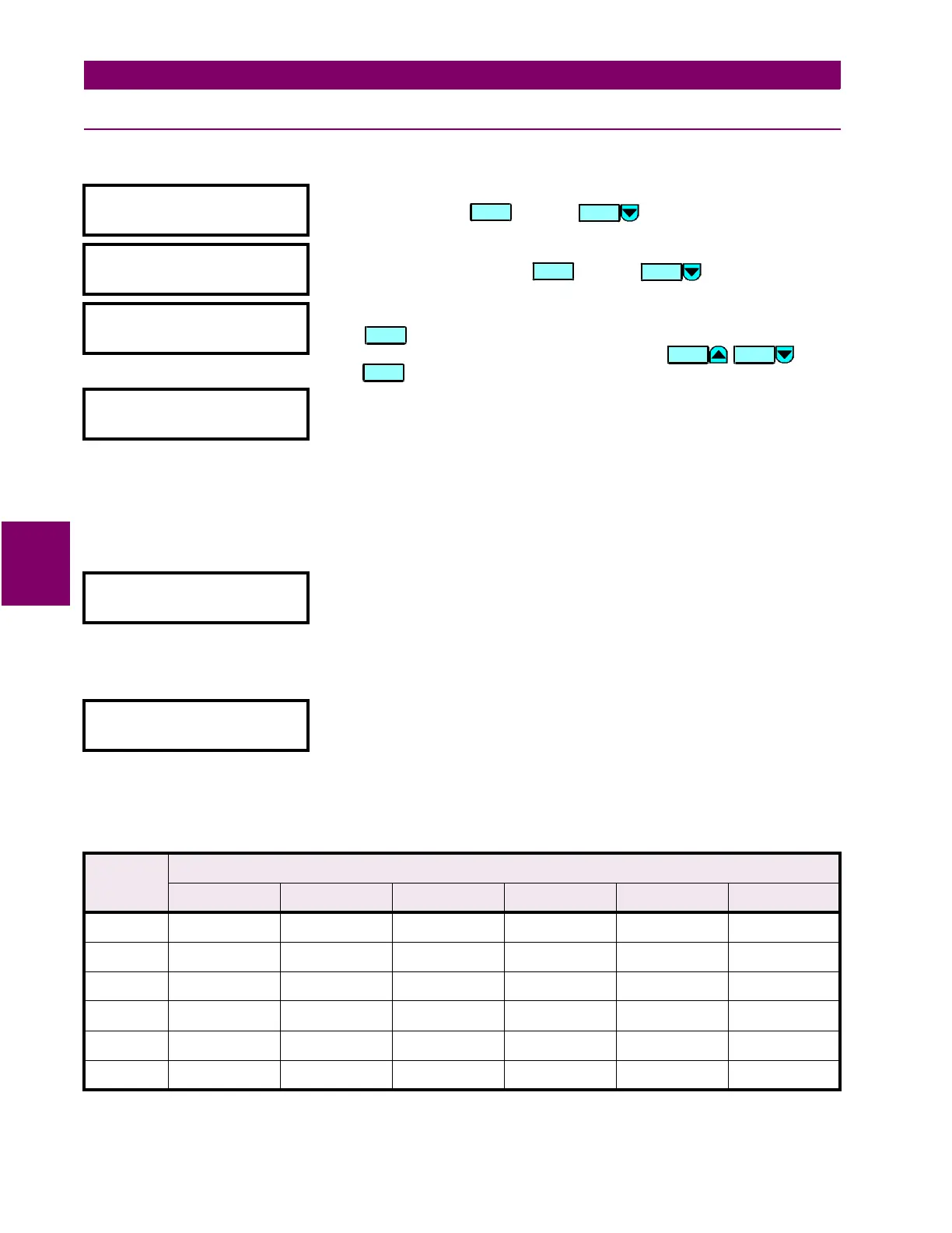
[ENTER] for more
This message indicates the start of the
OUTPUT RELAYS
section. To continue
these setpoints press or press for the next section.
y OUTPUT RELAY 1
y
[ENTER] for more
This message indicates the start of the
OUTPUT RELAY 1 (2-8)
section. To
continue these setpoints press or press for the next section.
OUTPUT 1 NAME:
Solid State Trip
Range: 18 alphanumeric characters
Press edit the name of the output. The text may be changed from
Solid State Trip
one character at a time, using the
/:
keys.
Press to store the edit and advance to the next character position.
OUTPUT 1 OPERATION:
Self-resetting
Range: Self-resetting / Latched
Select
Latched
to maintain the Output 1 (2-8) contacts in the energized state,
even after the condition that caused the contacts to operate is cleared, until
a reset command is issued (or automatically after one week). Select
Self-
reset
to automatically de-energize the contacts after the condition is cleared.
The solid state output (Output 1) remains closed until externally reset by a
momentary interruption of current, unless wired in parallel with an
electromechanical relay (Outputs 2-8) in which case it turns off when the
relay operates.
OUTPUT 1 TYPE:
Trip
Range: Trip / Alarm / Control
Select
Trip
to turn the TRIP indicator on or
Alarm
to turn the ALARM indicator
on when this output operates. Otherwise, select
Control
.
Note that the TRIP indicator remains on until a reset command is issued (or
automatically after one week). The ALARM indicator turns off automatically
when the output is no longer operated.
OUTPUT 1 FLEXLOGIC
01: Percent Diff OP
Range: any FlexLogic™ input or gate
The 20 messages shown in the table below are the parameters of the
FlexLogic™ equation for Output 1 (2-8) as described in the introduction to
FlexLogic™.
Table 5–8: OUTPUT RELAY DEFAULT FLEXLOGIC
FLEXLOGIC
GATE
OUTPUT RELAY NUMBER
1 to 3 4 5 6 7 8
01 Percent Diff OP Volts/Hertz 1 OP W1 THD Level OP Underfreq 1 OP Underfreq 2 OP Freq Decay 3 OP
02 Inst Diff OP Volts/Hertz 2 OP W2 THD Level OP Freq Decay R1 OP Freq Decay R2 OP END
03 Any W1 OC OP OR (2 inputs) Xfmr Overload OP OR (2 inputs) OR (2 inputs) END
04 Any W2 OC OP END 5th HarmLevel OP END END END
05 OR (4 inputs) END OR (4 inputs) END END END
06 to 20 END END END END END END
ENTER
MESSAGE
ENTER
MESSAGE
ENTER
VALUE VALUE
ENTER

 Loading...


