GE Power Management 745 Transformer Management Relay 5-37
5 SETPOINTS 5.4 S2 SYSTEM SETUP
5
5.4.5 HARMONICS
The 745 calculates the individual harmonics in each of the phase current inputs up to the 21
st
harmonic. With
this information, it calculates an estimate of the effect of non-sinusoidal load currents on the transformer rated
full load current. These calculations are based on ANSI/IEEE guide C57.110-1986, and require information that
is often only available from the transformer manufacturer’s test report, including the three-phase resistance of
each winding and the load loss at rated load. The harmonic derating factor will only be valid if this information
has been entered correctly.
The 745 also calculates the total harmonic distortion of the phase current input signals. The band of frequen-
cies over which this calculation is made can be changed to be more selective than the default 2
nd
to 21
st
har-
monics.
5.4.6 FLEXCURVES
Three programmed custom FlexCurves can be stored in the 745 as FlexCurve A, FlexCurve B and FlexCurve
C. This allows the user to save special curves for specific applications and then select them as required for
time overcurrent element curves. The custom FlexCurve has setpoints for entering the times-to-trip at various
levels of pickup. The levels are as follows: 1.03, 1.05, 1.1 to 6.0 in steps of 0.1, and 6.5 to 20.0 in steps of 0.5.
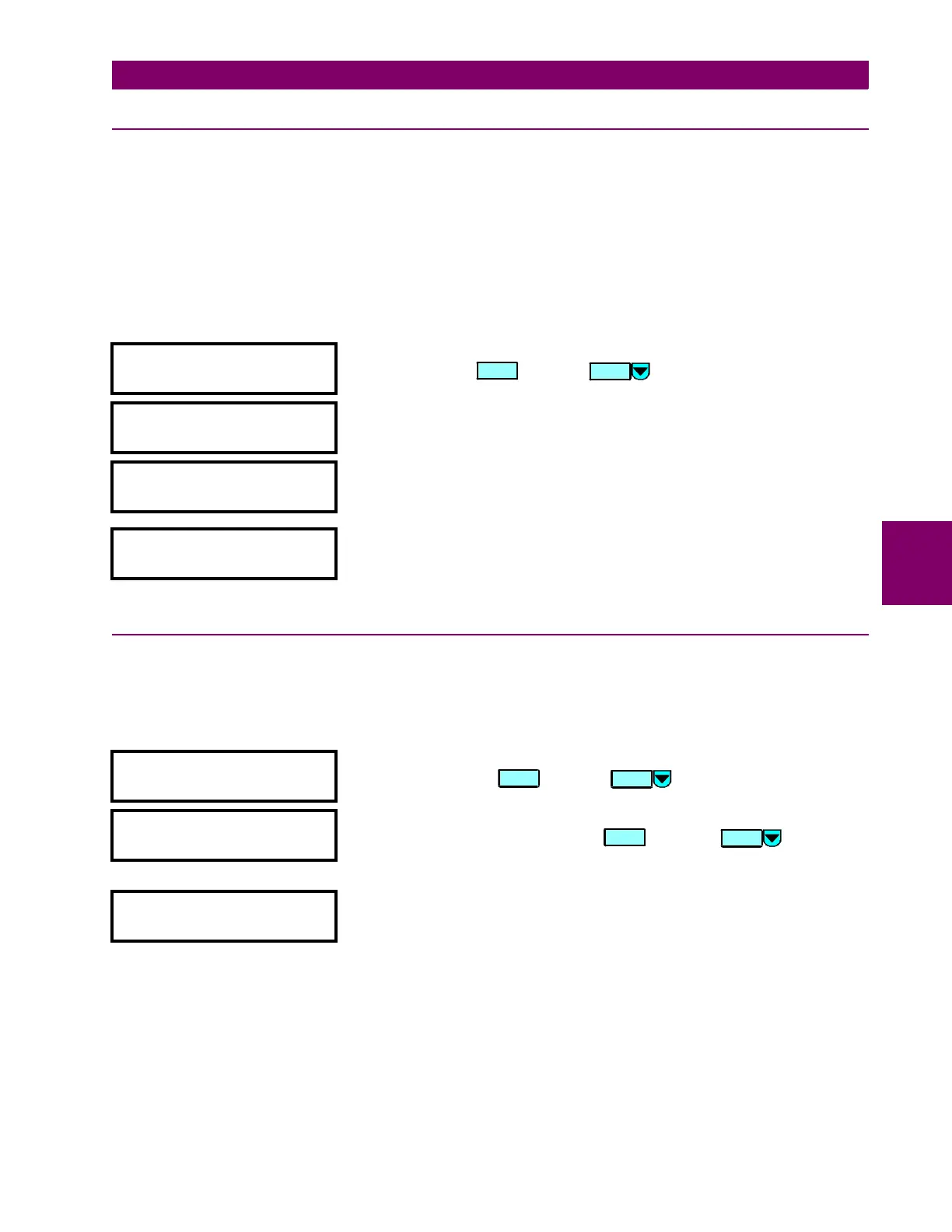
y HARMONICS
y [ENTER] for more
This message indicates the start of the
HARMONICS
section. To continue with
this setpoint press , or press to go to the next section.
HARMONIC DERATING
ESTIMATION: Disabled
Range: Disabled / Enabled
Enter
Enabled
to enable the harmonic derating factor calculations.
THD MINIMUM HARMONIC
NUMBER: 2
nd
Range: 2nd / 3rd / ... / 21st
Enter the minimum harmonic number of the frequency band over which total
harmonic distortion is calculated.
THD MAXIMUM HARMONIC
NUMBER: 21
st
Range: 2nd / 3rd / ... / 21st
Enter the maximum harmonic number of the frequency band over which total
harmonic distortion is calculated.
y FLEXCURVES
y [ENTER] for more
This message indicates the start of the
FLEXCURVES
section. To continue
these setpoints press , or press to go to the next section.
y FLEXCURVE A
y [ENTER] for more
This message indicates the start of the
FLEXCURVE A (B/C)
section. To
continue with these setpoints, press , or press to go to the
next section. Note that the messages for curve B and curve C are similar to
the following message shown for curve A.
CURVE A TRIP TIME AT
1.03 x PU: 0 ms
Range: 0 to 65000 (steps of 1)
Enter the trip time for 1.03 times the pickup level for curve A (B/C). The
messages that follow sequentially, correspond to the trip times for the
various pickup levels as indicated above.
ENTER
MESSAGE
MESSAGE
ENTER
MESSAGE

 Loading...


