5-28 745 Transformer Management Relay GE Power Management
5.3 S1 745 SETUP 5 SETPOINTS
5
5.3.6 RESETTING
The reset function performs the following actions: all latched relays are set to the non-operated state and
latched target messages are cleared, if the initiating conditions are no longer present. Resetting can be per-
formed in any of the following ways: via on the front panel while the 745 is in local mode (i.e. the LOCAL
indicator is on); via a logic input; via any of the communication ports. The following setpoints allowing configur-
ing some of the features associated with resetting.
5.3.7 CLOCK
The 745 includes a battery-backed internal clock that runs even when control power is lost. Battery power is
used only when the 745 is not powered. The battery is rated to last for at least 10 years continuous use. The
clock is accurate to within 1 minute per month. An IRIG-B signal may be connected to the 745 to synchronize
the clock to a known time base and to other relays. The clock performs time and date stamping for various
relay features, such as event and last trip data recording. Without an IRIG-B signal, the current time and date
must be entered in a new relay for any time and date displayed. If not entered, all message references to time
or date will display
Unavailable
. With an IRIG-B signal, only the current year needs to be entered.
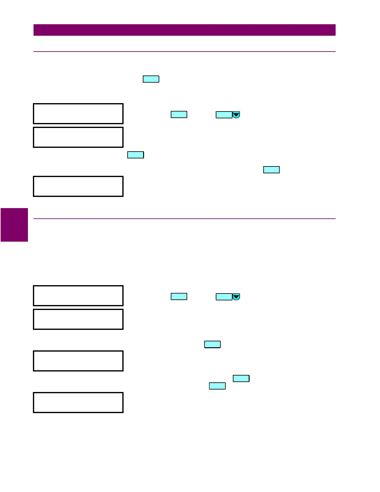
y RESETTING
y [ENTER] for more
This message indicates the start of the
RESETTING
section. To continue these
setpoints press , or press to go to the next section.
LOCAL RESET
BLOCK: Disabled
Range: Disabled / Logic Inpt 1 (2-16) / Virt Inpt 1 (2-16) / Output Rly 1 (2-8)
/ SelfTest Rly / Virt Outpt 1 (2-5)
The 745 is defaulted to the local mode. As a result, the front panel (local)
key is normally operational. Select any logic input, virtual input, output
relay, or virtual output which, when asserted or operated, will block local
mode, and hence the operation of the front panel .
REMOTE RESET
SIGNAL: Disabled
Range: Disabled / Logc Inpt 1 (2-16)
Select any logic input which, when asserted, will (remotely) cause a reset
command.
y CLOCK
y [ENTER] for more
This message indicates the start of the
CLOCK
section. To continue with these
setpoints press , or press to go to the next section.
DATE (MM/DD/YYYY):
01/01/1996
Range: Month = 1 to 12, Day = 1 to 31, Year = 1990 to 2089
Enter the current date, using two digits for the month, two digits for the day,
and four digits for the year. For example, April 30, 1996 would be entered as
04 30 1996. If entered from the front panel, the new date will take effect at
the moment of pressing the key.
TIME (HH:MM:SS):
00:00:00
Range: Hour = 0 to 23, Minute = 0 to 59, Second = 0 to 59
Enter the current time by using two digits for the hour in 24 hour time, two
digits for the minutes, and two digits for the seconds. The new time takes
effect at the moment of pressing the key. For example, 3:05 PM is
entered as 15 05 00, with the key pressed at exactly 3:05 PM.
IRIG-B SIGNAL TYPE:
None
Range: None / DC Shift / Amplitude Modulated
Select the type of IRIG-B signal being used for clock synchronization. Select
‘None’ if no IRIG-B signal is to be used.
R ESET
ENTER
R ES ET
R ESET
ENTER
ENTER

 Loading...


