5-86 745 Transformer Management Relay GE Power Management
5.7 S5 OUTPUTS 5 SETPOINTS
5
5.7.7 TIMERS
Protection and monitoring elements already have their own programmable delay timers, where they are
required. For additional flexibility, 10 independent timers are available for implementing custom schemes
where timers are not available. For example, a pickup delay timer may be required on a logic input; or, a single
delay timer may be required on the output of a block of logic.
This section contains the settings to configure timers 1 to 10.
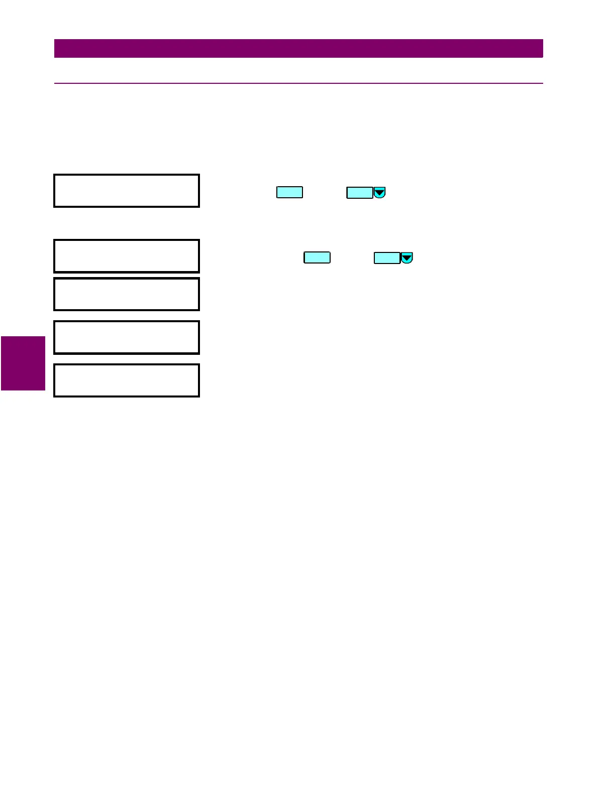
TIMER 1 (2-10)
y TIMERS
y
[ENTER] for more
This message indicates the start of the
TIMERS
section. To continue these
setpoints press or press for the next section.
y TIMER 1
y
[ENTER] for more
This message indicates the start of the
TIMER 1 (2-10)
section. To continue
these setpoints press or press for the next section.
TIMER 1 START:
END
Range: any FlexLogic input.
Select the FlexLogic entry which, when operated or asserted, will start timer
1 (2-10).
TIMER 1 PICKUP
DELAY: 0.00 s
Range: 0.00 to 600.00 (steps of 0.01)
Enter the delay time during which the start condition for timer 1 (2-10) must
remain operated or asserted, before the timer will operate.
TIMER 1 DROPOUT
DELAY: 0.00 s
Range: 0.00 to 600.00 (steps of 0.01)
Enter the delay time after which the start condition for timer 1 (2-10) must
remain not operated or not asserted, before the timer will stop operating.
ENTER
ENTER
MESSAGE
 Loading...


